|
|


 Arabic
 Bengali
 Chinese
 English
 French
 German
 Hebrew
 Hindi
Hindi Italian
 Japanese
 Korean
 Malay
Malay Polish
 Portuguese
 Spanish
 Turkish
 Ukrainian
 Vietnamese
|
ENCYCLOPEDIA OF RADIO ELECTRONICS AND ELECTRICAL ENGINEERING Interior lighting with super-bright LEDs. Encyclopedia of radio electronics and electrical engineering
Encyclopedia of radio electronics and electrical engineering / Automobile. Electronic devices The reliability of the car interior illuminator "Volga GAZ-3110" on a fluorescent lamp leaves much to be desired. In my car, the interior light failed in the second year of operation. Attempts to independently assemble a more reliable converter, similar to that described in the article by V. Kharyakov "Power supply for a fluorescent lighting lamp" ("Radio", 2006, No. 7, pp. 47, 48), brought only temporary success. The fluorescent lamp, normally working in the summer, stopped turning on with the onset of cold weather. For its reliable start, nevertheless, apparently, the incandescence of the electrodes is necessary. The appearance on sale of super-bright LEDs prompted the idea to replace them with a lamp in a car interior ceiling light. Typically, the LED is connected to a power source through a ballast resistor. A test of the purchased KIPD80 LEDs showed that the average forward voltage drop on each device is 3,5 V at an average forward current of 50 mA. Increasing the current in excess of 70 mA leads to the failure of the LED. Accordingly, the maximum power consumption of one LED is 0,175 watts. The calculation shows that with a supply voltage of 12 V and seven garlands of three LEDs connected in series and one 30 Ohm ballast resistor in each illuminator, the efficiency of the illuminator is 87,5%. But the on-board voltage in cars is rather unstable (in the GAZ-3110, a voltage change from 11 to 15 V is considered normal). At low voltage, when the headlights, glass heater and other consumers are turned on, the efficiency of such an illuminator is sharply reduced. With an increase in excess of 14 V, the current through the LEDs will exceed the maximum allowable, which will disable them. In this case, you can, of course, use 50 mA current stabilizers instead of ballast resistors, but the problem of working with a reduced on-board voltage remains. Therefore, it was decided to assemble a garland of twenty LEDs connected in series and feed it from a step-up flyback converter. Studying the experience of building LED lamps on the Internet determined the basis of the converter - an inexpensive and affordable microcontroller with pulse-width control. MS34063 (by ON Semiconductor) or its domestic counterpart KR1156EU5. Since the limit voltage of the output transistors of this microcircuit is 40 V, and a garland of twenty LEDs requires 70 V, an external high-voltage switching transistor was required, which was chosen as an IRL640 field-effect transistor with a maximum voltage of 200 V, a maximum current of 18 A and an open channel resistance of less than 0,18 ohm. Another argument in favor of this transistor was its short switching time.
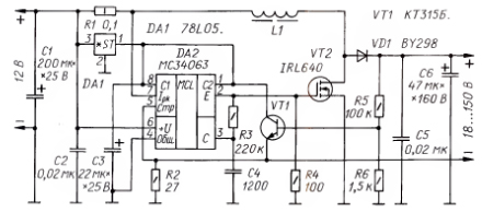
The schematic diagram of the converter is shown in fig. 1. Turning on the MC34063 chip has three differences from the typical one. First, the pre-output and output transistors of the microcontroller are connected to a micropower stabilizer 78L05 (DA1) for a voltage of 5 V, which is necessary to control the IRL640 transistor (in a typical circuit, they are connected directly to the power source). Feeding a string of LEDs with a stable current allows you to keep the level of power transmitted to it within a wide range of changes in the supply voltage. It also provides temperature compensation for the operating mode of the LEDs - as the temperature rises, the forward voltage drop across the LED decreases. Consequently, the power consumed by it is reduced. As a result of comfortable power supply conditions for LEDs - the reliability and longevity of their work. To limit the output voltage below the breakdown voltage of the IRL640 transistor, a protective device was introduced on the KT315B transistor with a voltage divider R5R6 in the base circuit. Transistor VT1 opens when the voltage at the output of the converter reaches about 150 V. This solution avoids the failure of the IRL640 transistor when the LED garland is turned off. The resistance of the resistor R1 was chosen on the basis of limiting the current through the IRL640 transistor at the level of 3 A. Due to the lack of resistors of this value on sale, it was made of two turns of nichrome wire with a diameter of 0,5 mm, wound on a drill shank with a diameter of 4,5 mm. The wire leads were tinned using phosphoric acid. The converter coil is made in the B18 armored magnetic circuit from the converter of the old fluorescent illuminator. It consists of 30 turns of PEV-2 0,3 wire. The coil is wound on the frame turn to turn, the layers are separated by a layer of capacitor paper. The gap between the cups of the magnetic circuit is performed using a washer cut out of office paper. The cups are tightened with a copper or brass MXNUMX screw. They also attach the magnetic circuit to the board. The frame of the coil is fixed inside the magnetic core with porous polyethylene washers. The IRL640 transistor is mounted on a homemade heat sink cut from a 1 mm thick copper plate. The side edges of the heat sink are notched, bent up and turned by 90 degrees with pliers. For better thermal contact between the transistor and the heat sink, heat-conducting paste is used. The heat sink with the transistor is attached to the converter board with a screw and an MXNUMX nut. The rectifier diode VD1 was chosen with a maximum reverse voltage of 400 V and a recovery time of 150 not only because it was commercially available. It heats up a little and reduces the efficiency of the converter. It is desirable to use diodes with a shorter recovery time (HER105 or SF18).
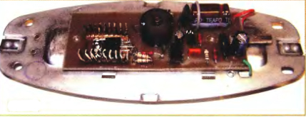
The converter board is made of foil fiberglass 1,5 mm thick. The board drawing is shown in fig. 2. The foil is etched only in narrow strips along the printed conductors, the remaining foil serves as a common wire connected to the car body (negative pole of the on-board voltage). To fasten the converter board to the base of the lamp, two MOH nuts are soldered to it, they also serve as contacts connecting the common wire of the board to the base. The contact for a standard 6,3 mm connector for connecting the positive on-board power wire to the board is also cut out of 1 mm thick copper sheet. It is attached to the board with a bracket made of copper wire with a diameter of 1 mm and soldered. The appearance of the board installed on the base of the illuminator is shown in fig. 3.
A garland of LEDs is assembled on a separate board from the same fiberglass. It is attached to the base of the illuminator instead of a fluorescent lamp on two bushings 5 mm long with two MOH screws, which are screwed into nuts soldered to the converter board. The LEDs are evenly placed on the board and connected in series according to. The garland is connected to the converter with two flexible MGTF wires. From the base of the illuminator, it is necessary to remove the fastening parts of the fluorescent lamp. The illuminator practically does not require adjustment and, with serviceable parts, it starts working immediately. There can be from six to forty LEDs in a garland. The measured efficiency of the converter is 75% with a power consumption of 4,29 W and, accordingly, a power in a garland of 3,22 W. Author: V. Gorbatykh, Ulan-Ude, Republic of Buryatia; Publication: radioradar.net
Machine for thinning flowers in gardens
02.05.2024 Advanced Infrared Microscope
02.05.2024 Air trap for insects
01.05.2024
▪ Who is tastier for a mosquito
▪ section of the site Electrician's Handbook. Article selection ▪ article Hang gliding snakes. Tips for a modeler ▪ article What agricultural output increases when exposed to lightning? Detailed answer ▪ article Black poplar. Legends, cultivation, methods of application
Home page | Library | Articles | Website map | Site Reviews
www.diagram.com.ua |


 Leave your comment on this article: