|
|


 Arabic
 Bengali
 Chinese
 English
 French
 German
 Hebrew
 Hindi
Hindi Italian
 Japanese
 Korean
 Malay
Malay Polish
 Portuguese
 Spanish
 Turkish
 Ukrainian
 Vietnamese
|
ENCYCLOPEDIA OF RADIO ELECTRONICS AND ELECTRICAL ENGINEERING Charger for car batteries
Encyclopedia of radio electronics and electrical engineering / Automobile. Electronic devices The charger circuit is presented on microcircuits of relative complexity. But if a person is at least a little familiar with electronics, he will repeat without problems. This charger was created for only one condition: the current adjustment should be from 0 to the maximum (a wider range of charging and battery types). Ordinary, even factory car chargers have an initial jump from 2,5-3 A and up to a maximum. The charger uses a thermostat that turns on the radiator cooling fan, but it can be excluded, this was done in order to minimize the size of the charger.  (click to enlarge) The memory consists of a control unit and a power unit. Блок управления The voltage from the transformer (trr) is approximately 15 V, it is supplied to the diode assembly KTs405, the rectified voltage is used to power the control of the D3 thyristor and to receive control pulses. Having passed the chain Rp, VD1, R1, R2, and the first element of the D1.1 microcircuit, we obtain pulses of approximately this shape (Fig. 1). Further, these pulses with the help of R3, D5, C1, R4 are converted into a saw, the shape of which is changed with the help of R4 (Fig. 2). Elements of the microcircuit from D1.2 to D1.4 align the signal (make it rectangular) and prevent the influence of the transistor VT1. The finished signal, passing through D4, R5 and VT1, is fed to the control output of the thyristor. As a result, the control signal, changing in phase, opens the thyristor at the beginning of each half-cycle, in the middle, at the end, etc. (Fig. 3). The regulation over the entire range is smooth. Both the microcircuit and the transistor VT1 receive power from KREN05. that is, it is a five-volt roll. It is necessary to fasten a small radiator to it. The roll does not get very hot, but heat removal is still needed, especially in the heat. Instead of the KT315 transistor, you can use the KT815, but you may have to pick up the resistance R5 if the thyristor does not open. Power unit Consists of thyristor D3 and 4 diodes KD213. Diodes D6-D9 are chosen for reasons that they are suitable for current, voltage and do not need to be screwed. They are simply pressed against the radiator with a metal or plastic plate. The whole thing (including the thyristor) is mounted on one radiator, and insulating heat-conducting plates are placed under the diodes and thyristor. I found very handy stuff in old burnt out monitors. It is also found in power supplies from computers. It feels like thin rubber to the touch. It is generally used in imported equipment. But of course you can use ordinary mica. (Fig. 4). In the worst case (so as not to bother), you can make your own separate radiator for each diode and thyristor. Then no mica is needed, but there should be no electrical connection of the radiators. Transformer Consists of 3 windings 1 - 220 V. 2 - 14 V, for control power 3 - 21 - 25 V, to power the power section. (powerful)  Setting They check the operation as follows: connect a 12 V light bulb to the charger instead of the battery, for example, from the dimensions of the car. By turning R4, the brightness of the light bulb should change from very bright to completely off. If the bulb does not light up at all, then reduce the resistance R5 by half (to 50 ohms). If the light does not go out completely, then increase the resistance R5. Add about 50-100 ohms. If the light does not light up at all and nothing helps, then bridge the collector and emitter of the transistor VT1 with a resistance of 50 ohms. If the light does not light up, the power section is incorrectly assembled, if it lights up, look for a malfunction in the control circuit. So, if everything is regulated and lights up, you need to adjust the charge current. The circuit has a resistance of 2 ohms wire. i.e. 2 ohm nichrome wire resistance. First, take the same, but at 3 ohms. Turn on the charger and short-circuit the wires that went to the light bulb and measure the current (using an ammeter). It should be 8-10 A. If it is more or less, then adjust the current using the wire resistance R wire. Nichrome itself can be 0,5-0,3 mm in diameter. Please note that during this procedure, the resistance heats up cool. It also heats up when charging, but not so much, this is normal. So ensure its cooling, for example, holes in the case, etc. But there will be no equal for those who like to search for crocodiles, spark as much as you like, there will be no charger. It is better to strengthen the resistance Rprov on a getinax (textolite) platform. And the last - about ventilation. The radiator cooling system is assembled from elements KREN12, C2, C3, VT2, R6, R7, R8 (surface mounting). By and large, it is not needed (unless, of course, you make a super mini charger), it's just a squeak of fashion. If you have a radiator (for example) made of an aluminum plate 120 * 120 mm, then this is enough to remove heat (the area of \u12b\u2ba factory radiator of this size is even large). But if you really want a fan, then leave one roll for 386 V, and connect a fan to it. Otherwise, you will have to chemistry with the transistor-sensor VT 486. It must be attached to the radiator also through insulating heat-conducting plates. I used a processor fan from a XNUMX processor, or from a XNUMX. They are almost the same. 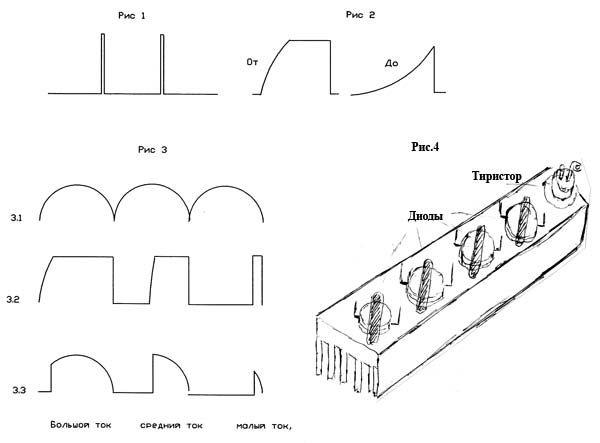 All device resistances are 0,25 or 0,5 watts. Two trimmers are marked with an asterisk. The rest of the values are indicated. It should be noted that if D213 or the like are used instead of KD232 diodes, then the winding voltage Trr 21 V must be increased to 26-27 V. Author: Fuganok; Publication: cxem.net
See other articles Section Automobile. Electronic devices
Artificial leather for touch emulation
15.04.2024 Petgugu Global cat litter
15.04.2024 The attractiveness of caring men
14.04.2024
▪ site section Cultivated and wild plants ▪ Electric magazines (annual archives) ▪ book Vacuum for science and technology. Ashkinazi L.A., 1987 ▪ article Science and education. Big encyclopedia for children and adults ▪ Article Carrying out work with increased danger ▪ reference Entering the foreign TV service mode. Book #18
Home page | Library | Articles | Website map | Site Reviews
www.diagram.com.ua |

 Leave your comment on this article: