|
|


 Arabic
 Bengali
 Chinese
 English
 French
 German
 Hebrew
 Hindi
Hindi Italian
 Japanese
 Korean
 Malay
Malay Polish
 Portuguese
 Spanish
 Turkish
 Ukrainian
 Vietnamese
|
ENCYCLOPEDIA OF RADIO ELECTRONICS AND ELECTRICAL ENGINEERING Transmitting prefix to the Katran receiver. Encyclopedia of radio electronics and electrical engineering
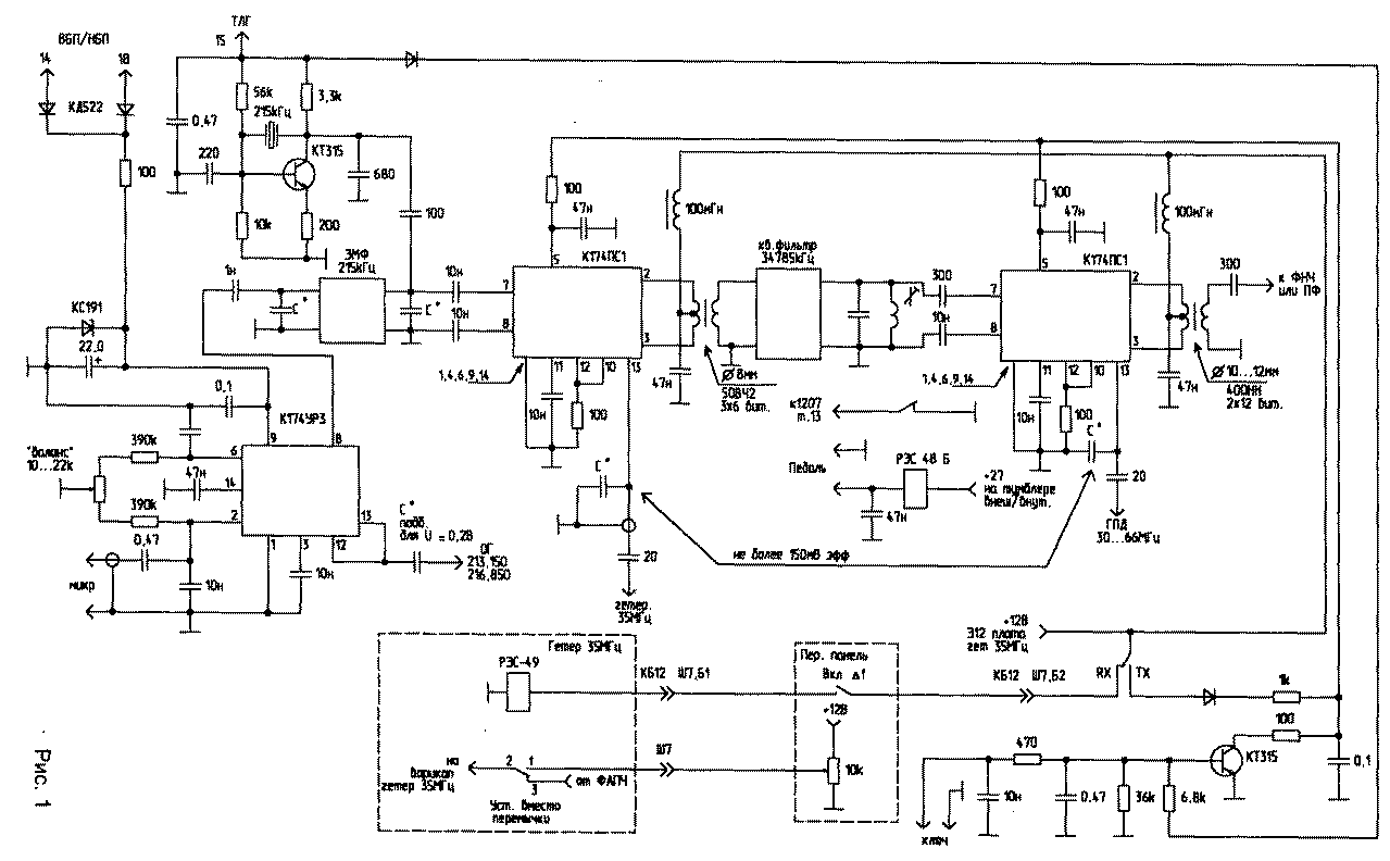
Encyclopedia of radio electronics and electrical engineering / Civil radio communications The first version of the set-top box, developed in 1993, requires intervention in the receiver circuit. It is intended for installation in the RPU of the "KATRAN" type (R-399 A) and is placed instead of the ULF board. This scheme provides for the presence of two scarce parts - EMF at 215 kHz with a band of 3 kHz and a quartz filter from "KATRAN" at 34785 kHz. The ULF board and the board with quartz 213,15 kHz and 216,85 kHz are removed from the block. The quartz is removed from the board and installed directly on the local oscillator board on the other side of the block. The set-top box board is located in the vacated compartment. The SSB driver is assembled on the K174URZ chip. Power is supplied to the microcircuit from the third local oscillator board through diodes from pins 14 and 18. This is done to automatically turn on the transmitter's SSB mode when the receiver is turned on in NBP or VBP mode. The mixers do not require adjustment, except for the selection of the local oscillator voltage using capacitive dividers in the range of 100 ... 200 mVeff. The capacitor through which the 35 MHz local oscillator signal is fed is installed in the compartment of this local oscillator, and the capacitance of the connecting cable is the second capacitor of the capacitive divider. The receiver's GPA voltage is taken from the GPA filters located in the adjacent compartment. Emitter or source followers are not required.
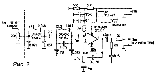
Telegraph manipulation is carried out at the conclusion 5 of the K174PS1 microcircuit. When the receiver is turned on in the TLG mode, a voltage of +12 V is supplied to a 215 kHz crystal oscillator, at the same time a key transistor opens, which shunts the power at the output of 5 mixers. During manipulation, the key transistor is locked and power is supplied to the control input of the mixers. In the presence of a quartz resonator at a frequency of 11,595 MHz (11,595x3 \u34785d XNUMX kHz), the telegraph operation of the set-top box can be built according to the scheme of the second option. At the output of the second mixer, it is desirable to use a low-pass filter with a cutoff frequency of about 30 MHz. You can use one of the schemes given in [1], or from the output 2 of the mixer, the signal can be fed directly to the power amplifier, at the input of which bandpass filters are installed. For receivers in which the 35 MHz generator is made using a PLL, it is possible to make the detuning mode within 1 ... 1,5 kHz at minimal cost. To do this, the technological jumper is removed from the output of the phase detector to the varicap and instead of it, a relay of the RES-49 type, etc. is installed. In the "transmit" mode, the contacts close the output circuit of the phase detector and the varicap, and in the "receive" mode and with the detuning turned on, the voltage from the detuning potentiometer is applied to the varicap. The "half-duplex" toggle switch is used as the detuning toggle switch, the detuning potentiometer is installed instead of the "executive-command" toggle switch. In this case, the wires suitable for the "half-duplex" toggle switch are used as follows: one goes to the winding of the detuning relay RES-49, the other to the RX contact of the receive-transmit relay. The wire going from the toggle switch to the body is connected to one of the detuning potentiometer leads. The detuning potentiometer is supplied with a voltage of 12 V (available on the type of work switch). A wire is connected to its engine, which previously went to the "executive-command" toggle switch. On block KB 16, this wire is disconnected from Ш1 to terminal 7 and connected to a free contact Ш4b (reciprocal Ш7 of block KB 12). From this contact, a wire is laid inside KB 12 to contact 1 of the RES-49 relay. For those receivers where the 35 MHz oscillator is made according to the multiplication scheme, the detuning mode can be ensured by turning off the 5 MHz signal from the reference oscillator in the receiving mode and applying the 5 MHz signal to the multiplier from the auxiliary crystal oscillator built according to the "frequency offset" scheme. In this case, if the 5 MHz generator is tuned to 1 kHz, the output frequency changes to 7 kHz. It is clear that in the "transmission" mode, the 5 MHz generator "Hyacinth" should be automatically connected. The switching scheme "reception-transmission" is shown in fig. one. Any relay with two groups of switching contacts and a winding of 27 V is applicable. To connect the pedal, any of the unused connectors on the back of the unit is used. The relay is installed next to the "external-internal" toggle switch. The +27 V power supply for the relay can be taken from the same toggle switch. One group of contacts completes the half-duplex circuit to lock the receiver in transmit mode. The second group supplies +12 V power to the transmitting part in the transmit mode and to the detuning relay in the receive mode through the "detuning" toggle switch, if the latter is in the "on" position. As a ULF, preference was given to the K174UN19 chip. The use of this microcircuit is due to the fact that it requires a minimum of attachments, much less "noise" (compared to the "KATPAH" ONS), and the same voltage of +27 V is used to power it, which was previously used to power the ULF receiver, which provides a more correct load distribution of the power supply (Fig. 2).
All the power that K174UN19 can give to the load is not required, and in order not to overload the +27 V source, a 20 ... 30 Ohm resistor is included in the ULF load circuit, because. the current consumption decreases in proportion to the increase in load resistance. At the ULF input, it is very useful to turn on a switchable low-pass filter made on the basis of inductances used in well-known D-3,4 filters. With open contacts of relay K1, the filter band is about 3,5 kHz, and with closed contacts, about 1,5 kHz. To switch, the "LF BAND" switch on the front panel of the receiver was used. If there is a need to retain existing bass bands, the switch should be four positions. It is better to install the ULF board under the front panel, because. at the same time, there is no need to do additional installation, and there will be more space in the ULF compartment to accommodate the elements of the set-top box .. The ULF input signal is supplied from the "LF GAIN" potentiometer, the output is connected to the "TLF" jacks, +27 V is supplied from the "CONTROL" switch, the "LF BAND" switch is located there. Due to the fact that changes in schemes and options occur during the finishing process, as well as due to the use of different types of parts, printed circuit board drawings are not given. The layout of printed circuit boards is made individually for each variant of the selected circuits and available parts. In the author's version, the prefix was used with the PA unit of the R-140 radio station. TV interference was not observed, with a high-quality microphone (MD-80, MD-380) and the correct matching of the EMF input and output, the signal quality was impeccable. The second version of the set-top box is designed for radio amateurs who do not want to interfere with the receiver circuit. The SSB signal is formed at a frequency of 500 kHz with its subsequent transfer to the frequency of the "KATRANA" IF - 34785 kHz - using a 34285 kHz (35285 kHz) base generator. Due to the fact that the long-term stability of this generator is still insufficient, its adjustment is applied using a potentiometer on the front panel of the set-top box. The only scarce detail is the IF filter "KATRANA" at a frequency of 34785 kHz, because. It is quite difficult to "cut off" the mirror channel with the help of LC filters at a given ratio of mixed frequencies. Only the GPA signal is supplied from "KATRAN" without the use of a source or emitter follower, if a connecting cable of short length is used. On the rear wall, the local oscillator jumper is removed, a coaxial tee is installed, and the tap goes to the prefix (this is how it was done for UA1ZA). Schematic diagram of the attachment - fig.3-1 (18 Kb) Schematic diagram of the attachment - fig.3-2 (25 Kb) In the SSB-shaper on the K174URZ chip, the setting comes down to setting the balance with a tuning resistor, its value is chosen small for greater balance accuracy, but if it is in one of the extreme positions, you need to select the fixed resistors in its shoulders. Their absolute value is not critical and can be in the range of 200 ... 500 kOhm. At the output, the DSB signal is usually in the range of 0,5 ... 2,0 V. After selecting the capacitors at the input and output of the EMF, the limitation mode should be set. In the left (according to the diagram) position of the resistor slider, the limitation will be "softer". To increase the degree of limitation, one diode can be left in each chain, then the voltage at the output of the op-amp is about 0,6 V, i.e. approximately equal to the turn-off voltage of the diodes. If there is no second EMF, the limiter can be omitted and points A and B can be bridged. The 11428 kHz quartz resonator in the first converter was used from the SHIP radio station of the 16th channel (F = 11435 kHz). Its frequency was adjusted to the required value by rubbing the silver coating with soft solder. The local oscillator frequency (34283,150 kHz) must be set in the middle position of the transmitter tuning resistor, controlling your signal at the IF frequency or operating range using your own receiver, because. 174PS1 does not have an output for controlling the local oscillator, and the frequency counter probe connected to the local oscillator outputs "leads" its frequency. Similarly, the frequency of the telegraph oscillator quartz is adjusted. If there is no suitable quartz, the operation of the TLG can be ensured by applying a 47 kHz signal with a level of 82 ... 500 mV through a 50 ... 150 pF capacitor to the input of the first mixer (point B) from an LC or crystal oscillator. But it should be noted that due to the high quality factor of quartz and its low frequency, the increase in the amplitude of the generator occurs slowly, therefore, in this case, the manipulation must be carried out in subsequent stages. Instead of a low-pass filter at the output of the second mixer, band-pass filters can be used, and a transistor amplifier can be used instead of a tube one. At the output of the second mixer, the signal voltage usually lies in the range of 0,5 ... 0,8 V. Based on this, and to obtain the required power, an amplifier circuit is selected. You can do without a 34785 kHz crystal filter, but then the SSB signal must be generated at higher frequencies, for example 5,5 MHz or 9,0 MHz, then also transferred to a frequency of 34785 kHz using a crystal oscillator to the appropriate frequency, and then a mirror the channel will be far enough away, and at a frequency of 34785 kHz you can get by with the usual three-bit FSS. You can generate an SSB signal at 500 kHz, then transfer it to a frequency of, for example, 10,7 MHz, then transfer it to a frequency of 34785 kHz and filter with an LC filter. In this option, you will need another mixer, similar to that made in this attachment. In general, this circuit was tested as attachments to many types of RPU and differs only in conversion frequencies and the use of both its own filters and the filters of the RPU itself, and showed ease of setup, high quality and reliability. With minimal time, those who have a UA1FA transmitting prefix can make a prefix, because. the main labor-intensive nodes (power supply, driver, PF, output stage) are already there. Literature 1. Radio amateur. KB and VHF. - 1996. - No. 3. -S.30. Author: Yu.Zavgorodniy (RA1ZW), Murmansk; Publication: N. Bolshakov, rf.atnn.ru
Machine for thinning flowers in gardens
02.05.2024 Advanced Infrared Microscope
02.05.2024 Air trap for insects
01.05.2024
▪ Payment cards with built-in fingerprint scanner ▪ Insulated Gate Bipolar Transistor FGA25N120ANTD ▪ Cranberries delay the development of cancer
▪ section of the site Personal transport: land, water, air. Article selection ▪ article Theater for yourself. Popular expression ▪ Article How many fingers does a two-toed sloth have? Detailed answer ▪ article Veneer and facing materials cutter with scissors. Standard instruction on labor protection ▪ article 144 MHz car antenna. Encyclopedia of radio electronics and electrical engineering
Home page | Library | Articles | Website map | Site Reviews
www.diagram.com.ua |

 Leave your comment on this article: