|
|


 Arabic
 Bengali
 Chinese
 English
 French
 German
 Hebrew
 Hindi
Hindi Italian
 Japanese
 Korean
 Malay
Malay Polish
 Portuguese
 Spanish
 Turkish
 Ukrainian
 Vietnamese
|
ENCYCLOPEDIA OF RADIO ELECTRONICS AND ELECTRICAL ENGINEERING Adaptive control device for car seat heater. Encyclopedia of radio electronics and electrical engineering
Encyclopedia of radio electronics and electrical engineering / Automobile. Electronic devices Every motorist is well aware of how unpleasant it is to sit in the cold seat of an unheated car in winter. Among other things, it is also harmful to health, as it can provoke a number of serious diseases. There are various capes and covers for heating seats, and in prestigious car models, seats usually have built-in heaters. But it should be noted that sitting on a warm chair for a long time is also harmful. Therefore, more or less serious heaters have a timer that turns off the heating after a while. Moreover, this time, as a rule, is fixed or, at best, has manual adjustment. And manipulations with it while driving can lead to a traffic accident. To automate the setting of the optimum temperature, you can use the thermostatic chair. But here there are difficulties with measuring the actual temperature of the surface of the chair and the problem of where to install the sensor so as not to mechanically damage it during operation. Another option is to relate the duration of the chair warmer to the ambient temperature. The lower it is, the longer the heater should work, and in warm weather it is not required to turn it on at all. The temperature-duration dependence of the heater will have to be selected experimentally. On fig. 1 shows a diagram of a device operating according to such an algorithm. It contains a voltage regulator on the DA1 chip, a temperature sensor BK1, a microcontroller DD1 and a powerful key on a field-effect transistor VT1 in the power circuit of the heater EK1.
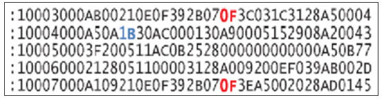
The device is powered by 12 V from the cigarette lighter socket. This voltage is supplied to the integral stabilizer DA1, and then the stabilized voltage of 5 V feeds the digital temperature sensor BK1 and the microcontroller DD1. After the supply voltage appears, the microcontroller instructs the sensor to measure the temperature and reads the received value. If it is below Tн (initial switch-on temperature), then the microcontroller opens the field-effect transistor VT1 for a certain time, including the heater BK1. In the device under consideration, this time is directly proportional to the difference Tн and ambient temperature T measured by the sensor: t = (Tн - T) k, where t is the duration of the heater, s; k is the proportionality factor, second per degree Celsius. After turning off the heater, the process will be repeated only after turning off and then turning on the power of the device. In most foreign-made cars, when the ignition is turned off, the voltage is removed from the cigarette lighter socket, and it is not necessary to disconnect the heating device from it. In domestic cars, where the voltage at the cigarette lighter socket does not depend on the position of the ignition switch, you will have to find a way to connect the heating device so that it turns off when the ignition is turned on. Otherwise, to restart the device, you will have to turn it off for a few seconds manually each time, and then turn it on. The table shows a fragment of the HEX-file of the DD1 microcontroller program. Bytes containing temperature values Tнare highlighted in red in the rows of the table. In this case, it is set to +15 °С (0FH). The byte containing the coefficient of proportionality k is highlighted in blue. The unit of its value corresponds to approximately 1,1 s/°C.
When making changes to the HEX file, do not forget to change the checksum (the last byte of the string) along with the value of the byte in the string. The checksum should be reduced by the same number of units as the byte was increased, or vice versa. The available number 1BH corresponds to 30 s/°C. This means that at an ambient temperature of +15 °C and above, the heating will not turn on at all, at a temperature of +14 °C it will turn on for 30 s, at a temperature of + 13 °C - for 60 s, at a temperature of + 12 °C - for 90 s, etc. By changing these bytes, you can choose the most comfortable heating mode. The author tested two constructive versions of the device. In the first one, a heated cape "ZHARA" HOT-550GY was used (Fig. 2). From its back side, you need to unfasten the zipper, fixed with several stitches of thread. Then carefully remove the adhesive strip from the control panel, remove the control unit and remove the old printed circuit board from it.
A drawing of a new printed circuit board and the placement of elements on it are shown in fig. 3. Resistors R1, R3 and capacitors C3 and C4 are 0805 SMT. Capacitors C1 and C2 can be ceramic or oxide. Resistor R2 - any power of 0,125 watts. For a microcontroller, a panel must be installed on the board. The resistance of the field effect transistor IRF2804 in the open state is very small. Therefore, even with a current of several amperes, the power dissipated by it will not exceed tenths of a watt, and it does not require heat removal.
The board installed in the body of the cape control unit is shown in fig. 4. The hole in the front panel above the microcontroller is enlarged to make it easier to remove the microcontroller if it needs to be reprogrammed (Fig. 5). At the end of the adjustment of the device, the old overlay on its front panel is glued into place.
In the second variant, the simplest domestic heater "Emelya" is used without any modifications. In this case, the heating device board is made according to the drawings in Fig. 6. It is designed to install all resistors and capacitors of sizes 0805 and 1206 and the PIC12F629-I / SN microcontroller in the SO-8 package. Instead of a 4 MHz quartz resonator, a ceramic CSTCC4M00G56 / 53-R0 was used at the same frequency with capacitors built into it, replacing capacitors C3 and C4.
According to the Murata catalog, such resonators are produced at a frequency of no more than 3,9 MHz. However, in online stores they are also available at a frequency of 4 MHz. The board with the programmed microcontroller installed on it is built into the cigarette lighter plug, as shown in Fig. 7. As FU1, the 7 A fusible link in the heater was used.
In both versions of the device, the KIPD 66 E-K LED can be replaced by any other of a suitable size, glow color and brightness. Board drawings in Sprint Layout 5.0 format and microcontroller program: ftp://ftp.radio.ru/pub/2015/04/aha.zip. Author: S.Zorin
Artificial leather for touch emulation
15.04.2024 Petgugu Global cat litter
15.04.2024 The attractiveness of caring men
14.04.2024
▪ Panasonic self-managed refrigerator ▪ Created a unique cold matter ▪ Application of Ara Modular Smartphone Components for Wearable Electronics
▪ section of the site Wonders of nature. Article selection ▪ article Topographic anatomy. History and essence of scientific discovery ▪ article What are the causes of reflexes? Detailed answer ▪ article Pedunculate oak. Legends, cultivation, methods of application ▪ article The disappearance of a glass of water. Focus Secret
Home page | Library | Articles | Website map | Site Reviews
www.diagram.com.ua |


 Leave your comment on this article: