|
|


 Arabic
 Bengali
 Chinese
 English
 French
 German
 Hebrew
 Hindi
Hindi Italian
 Japanese
 Korean
 Malay
Malay Polish
 Portuguese
 Spanish
 Turkish
 Ukrainian
 Vietnamese
|
ENCYCLOPEDIA OF RADIO ELECTRONICS AND ELECTRICAL ENGINEERING Voltage stabilizer for heavy motorcycles. Encyclopedia of radio electronics and electrical engineering
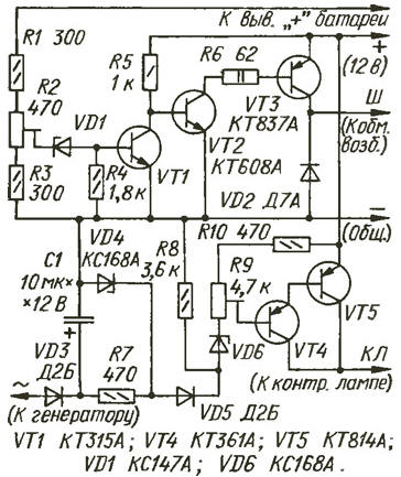
Encyclopedia of radio electronics and electrical engineering / Automobile. Electronic devices The advantage of the electronic on-board voltage stabilization system over the electromechanical one is its high reliability, the ability to quickly and conveniently set the generator voltage, and the absence of the need for any preventive operations associated with the operation of the stabilizer. Electronic stabilizers have been used on cars for a relatively long time, and now motorcycles are also being equipped with them. One such device is described in this article. The stabilizer is intended for installation on heavy motorcycles "Dnepr" and "Ural", in which the source of electricity is a G-424 synchronous generator, and the voltage is stabilized by a serial electromechanical relay-regulator RRZZ0. On-board voltage is 12 V. The described device is a stabilizer itself and an indication unit for the generator operating mode. The stabilizer is assembled on the basis of a device [1], which has already become standard. The measuring element is VD1, VT1, and the amplification element is VT2, VT3 (see diagram). Diode VD2 serves to protect transistor VT3 from high-voltage self-induction pulses of the excitation winding that occur when the transistor is quickly closed.
The indication unit consists of a transistor switch-current amplifier VT4VT5, loaded with a control lamp CL (not shown in the diagram), a threshold device assembled on elements R8-R10, VD6, an overvoltage detector R7VD4VD5 and a rectifier VD3 with a smoothing capacitor C1. A relative disadvantage of the stabilizer is that when the battery voltage decreases below 7 V, the control lamp will not light up. But this with a battery whose nominal voltage is 12 V is only possible in the event of an emergency discharge, which is fraught with sulfation of the plates. While the generator voltage is low, transistor VT1 is closed, and VT2 and VT3 are open and current flows through the generator excitation winding, which causes the generator voltage to increase. As soon as it reaches the nominal level, the zener diode VD1 opens. This will lead to the opening of transistor VT1, the closing of transistors VT2, VT3 and the cessation of current through the field winding. As a result, the generator output voltage begins to decrease. As soon as it decreases to a value at which the zener diode VD1 closes, transistor VT1 closes, and VT2 and VT3 open, resuming the current through the generator excitation winding, the voltage at its output will begin to increase again. The described processes are repeated, and the on-board voltage fluctuates within very narrow limits around the nominal value, which is set by trimming resistor R2. When the ignition is on, but the engine is not running, the voltage applied to the zener diode VD6 exceeds its stabilization voltage, so the composite transistor VT4VT5 is open, and current flows through the control lamp. The voltage across resistor R8 is about 5 V. As soon as the engine starts, an alternating voltage will appear at the “~” terminal (generator phase output) - it is approximately 5,5 V relative to the motorcycle body [2]. After rectification by diode VD3 and smoothing by capacitor C1, it will be applied to resistor R8, and the voltage on the zener diode VD6 will become lower than the stabilization voltage, it will close, which means that the composite transistor VT4VT5 will also close - the control lamp will go out. If the generator voltage, increasing, exceeds a value of approximately 14 V, the zener diode VD4 will open and the voltage at the anode of the diode VD5 will no longer increase. The voltage at the +12 V pin will increase, as a result the zener diode VD6 will open, followed by the composite transistor VT4VT5. Diode VD5 prevents resistor R8 from being shunted by zener diode VD4 in operating modes. In cases where overvoltage signaling is not required, elements R7, VD4, VD5 must be excluded. The stabilizer is not critical to the parameters of the components. Transistors VT1, VT4 can be replaced with any low-power transistors of the appropriate structure, VT2 - medium power, VT3, VT5 - powerful, as long as their static current transfer coefficient is more than 10. Transistors VT3 and VT5 must be installed on heat sinks. The zener diode VD1 can have a voltage in the range of 3...10 V, but preferably with a negative temperature coefficient of the stabilization voltage, which will provide a slight increase in the generator voltage as the temperature decreases. Zener diodes KS168A (VD4, VD6) can be replaced with KS168V. Fixed resistors - MLT, trimmers - any. Capacitor C1 - any oxide. Diodes D2B (VD3, VD5) can be replaced with any low-power diodes with a direct current of at least 10 mA, and D7A (VD2) can be replaced with any of the D7, D226, KD105 series. A correctly assembled device does not require adjustment; you only need to set the rated voltage of the generator and the response voltage of the generator overvoltage alarm unit. To do this, you need to connect a voltmeter directly to the battery. With the engine running, set the generator voltage with resistor R2 at about 13,7 V. Make sure that with a significant increase in engine speed it does not exceed 14 V. Next, by closing the “+” and “W” terminals and increasing the engine speed so that the voltage becomes 14,5 V, use resistor R9 to set the control lamp to glow dimly. Open the “+” and “W” clamps and make sure that at a voltage of 14 V the lamp goes out completely, and when the voltage increases above 14,5 V it shines at full intensity. The stabilizer is mounted and installed on the Ural motorcycle in a separate box next to the existing relay regulator. Operation of the device for several years has shown its reliable and stable operation. There was no need for additional adjustment. Literature
Author: A.Staroverov, Vologda
Artificial leather for touch emulation
15.04.2024 Petgugu Global cat litter
15.04.2024 The attractiveness of caring men
14.04.2024
▪ Compact medical power supplies Mean Well RPS-400 ▪ Headphones JBL LIVE Pro 2, LIVE Free 2 and Reflect Aero
▪ section of the site Riddles for adults and children. Article selection ▪ article by Alphonse de Lamartine. Famous aphorisms ▪ article Are lizards poisonous? Detailed answer ▪ article Locksmith construction. Standard instruction on labor protection ▪ article Electro-fluvial chandelier. Encyclopedia of radio electronics and electrical engineering
Home page | Library | Articles | Website map | Site Reviews
www.diagram.com.ua |

 Leave your comment on this article: