|
|


 Arabic
 Bengali
 Chinese
 English
 French
 German
 Hebrew
 Hindi
Hindi Italian
 Japanese
 Korean
 Malay
Malay Polish
 Portuguese
 Spanish
 Turkish
 Ukrainian
 Vietnamese
|
ENCYCLOPEDIA OF RADIO ELECTRONICS AND ELECTRICAL ENGINEERING Modernization of the ignition unit. Encyclopedia of radio electronics and electrical engineering
Encyclopedia of radio electronics and electrical engineering / Automobile. Ignition Many years of operation on domestic and foreign cars of electronic ignition units, assembled according to the article by Yu. Sverchkov [1] with improvements proposed by G. Karasev [2], showed that these improvements, together with positive qualities (increased spark duration, for example), lead to failures in sparking at a crankshaft speed of 3000 min-1 or more. Moreover, it turned out that it is extremely difficult to completely eliminate these failures, even if the recommendations given in [3] are strictly followed. At the stage of setting up the unit, it was found that the appearance of a voltage half-wave on the “K” terminal of the ignition coil after closing the VD5 diode (the designations of the elements hereinafter correspond to the diagram in Fig. 1 in [2]) is extremely unstable. The characteristics of this half-wave strongly depend not only on the values of the capacitor C2 and resistor R4, but also on the supply voltage, and to an even greater extent on the width of the spark gap.
After installing the unit on the car, adjusted and operating on the stand without failures in the pulse shaper frequency range of 10 ... . Neither a different combination of the capacitance values of the capacitor C200 (from 3 to 14 μF) and the resistance of the resistor R7 (from 2 to 0,01 Ohms) helped, nor even the selection of the trinistor VS0,047 for control current. Failures completely disappeared when the value of the resistor R4 was over 1,5 kOhm and the capacitor C2 was 0,01 μF, i.e., with single-period sparking in accordance with the block diagram of Yu. Sverchkov. For several years, the unit worked flawlessly with the C2R3R4VD6 spark extension circuit removed. Analysis of the oscillograms of the voltage at the terminal "K" of the ignition coil, obtained on the ignition unit installed in the car with a spark extension circuit, at different sparking frequencies, leads to the conclusion that the cause of failures in sparking lies in the instability of the rate of rise of the voltage half-wave on capacitor C3, the following behind the closing of the diode VD5. Therefore, we have to admit that the method of increasing the duration of the spark discharge with a trinistor-capacitor unit by applying a repeated opening pulse to the control electrode of the trinistor, formed by the residual voltage on the storage capacitor, is unsuitable for practical use in a car. It was possible to put into practice the idea of increasing the duration of a spark discharge in a capacitor ignition unit [1] due to the use of a powerful composite transistor KT898A instead of a trinistor, specially designed for automotive ignition systems. The scheme of the upgraded unit is shown here in Fig. 1 (hereinafter, the designations of the elements correspond to this scheme). The control circuit for the discharge of the storage capacitor C2 is significantly simplified in comparison with [2]. The charging time constant of the control capacitor C3 is determined by the values of the elements C3 and R3 and the resistance of the diode VD7, and the discharge is determined by C3 and R4, VD6 and the resistance of the emitter junction of the transistor VT2. The base current of the transistor VT2 depends on the voltage across the capacitor C3, the resistance of the diode VD6, the resistor R4 and the supply voltage, which allows you to set up the unit in bench conditions. For adjustment, the unit is connected to an adjustable power source with a voltage of up to 15 V and with a load current of 3 ... 5 A and to the ignition coil, a spark gap of 7 mm is set between its central terminal and the "B" terminal. To pin 6 of connector X1.1 connect the output of the shaper of rectangular pulses with a duty cycle of 3 and a load capacity of at least 0,5 A. It is very convenient to use an octane corrector [4] with auxiliary devices for adjustment (you just need to close the variable resistor R6 according to Fig. 1 in [4]. In the unit being adjusted, instead of the constant resistor R3, a variable with a nominal value of 2,2 kOhm is connected, setting its slider to the position maximum resistance Turn on the power supply for a voltage of 14 V and apply control pulses with a frequency of 10 to 200 Hz to the input, controlling the shape of the voltage at the terminal "K" of the ignition coil with an oscilloscope - it must correspond to that shown in Fig. 2.
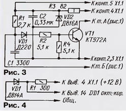
If only one period of voltage fluctuation is visible on the oscillogram, by rotating the variable resistor slider, a second period is achieved with a mandatory visible clear boundary for the end of sparking. Then reduce the supply voltage to 12 V and repeat the previous operation. After that, a control check of operation at a frequency of 10 ... 200 Hz at a supply voltage of 12 ... 14 V is carried out. The resistance of the introduced part of the variable resistor is measured and a constant resistor of the nearest rating is soldered. Usually, the resistance R3 is in the range from 200 to 680 ohms. In some cases, it may be necessary to select the capacitor C3 within 1 ... 3,3 uF. Reducing the charging time constant of the capacitor C3 due to the resistor R3 does not impair the protection of the block from the impulses of "bounce" of the breaker contacts, since the "bounce" process is shorter than the time during which the base current of the transistor VT2 reaches a value sufficient to open it. When using the block in conjunction with an octane corrector [4; 5] interference associated with "bounce" is suppressed even more reliably. The capacitance of the storage capacitor C2 of the ignition unit has been increased to 2 microfarads in order to increase its discharge time. In this case, the duration of the first discharge period is 0,4 ms. In order for the capacitor to have time to charge before the next sparking cycle, the converter in the block must be forced by increasing the thickness of the set of plates of the transformer T1 to 8 mm, and when setting up the block according to the method of Yu. Sverchkov, by selecting resistor R1, achieve a voltage of 150 ... 160 V on the capacitor C2 (in this case, the capacitor must be shunted with a resistor with a resistance of 1,5 kOhm with a power of at least 5 W). In this embodiment, the converter in the block continues to work reliably for more than 6 years. Diode VD5 according to the scheme of fig. 1 in [2] is excluded from the block; its function is performed by the built-in protective diode of the transistor VT2 of the block. Capacitor C2 - MBGO, C3 - K53-1 or K53-4, K53-14, K53-18; aluminum capacitors cannot be used due to the high leakage current and low reliability. The KT898A transistor can only be replaced with KT897A, KT898A1 or foreign BU931Z, BU931ZR BU931ZPF1, BU941ZPF1. Connector X1 consists of an ONP-ZG-52-V-AE insert and an ONP-ZG-52-R-AE socket. The described block can be used in cars of the VAZ-2108 and VAZ-2109 families, for which it will be necessary to connect to the block to the left of the X1.1 connector according to the diagram in Fig. 1 matching node, assembled according to the scheme in fig. 3 (the cross marks the point of the chain break). If it is supposed to use an octane corrector [5] together with the ignition unit, resistors R1, R4 and capacitors C1, C2 should be excluded from the matching unit, resistor R2 and diode VD1 should be closed and the output of the octane corrector [5] (resistor R7) should be connected to base transistor VT1 node. The Zener diode D816A must be replaced with D815V, the positive power wire of the corrector should be connected to pin 5 of connector X1.1. Capacitors in node C1 - KM-5 (KM-6, K10-7, K10-17), C2 - K73-9 (K73-11). When using the unit on cars of other types that have a contact breaker, a parametric voltage stabilizer should be installed to power the octane corrector, fig. 4.
The output of the breaker capacitor Spr is disconnected and soldered to pin 7 of socket X1.2. Now, to switch to conventional ignition, it is enough to insert a plug-plug X1.2 into socket X1.3, in which contacts 1,6,7 are connected together (it is not shown in the diagram in Fig. 1). In order not to output the wire from the breaker capacitor Spr to the X1.2 socket in the X1.3 plug, it is possible to provide a capacitor C4 K73-11 with a capacity of 0,22 μF for a voltage of 400 V by connecting it between pins 1, 6, 7 and pin 2. In this case, the capacitor Spr is simply dismantled. After carrying out the specified modernization, the unit provides uninterrupted sparking with two periods with a total spark duration of at least 0,8 ms at an engine crankshaft speed of 30 to 6000 min-1 and a change in the voltage of the car's on-board network from 12 to 14 V. The engine began to work "softer ", improved the dynamics of the car. When the supply voltage is reduced to 6 V, the unit maintains uninterrupted sparking with one period within the specified limits of the crankshaft speed, and two-period sparking is maintained up to a speed of 1500 min-1 with a decrease in the on-board voltage to 8 V, which greatly facilitates engine start. The use of a switching transistor instead of a trinistor in the unit also makes it possible to increase the spark energy due to the almost complete discharge of the storage capacitor through the primary winding of the ignition coil, as in capacitor ignition units with pulsed energy storage. This option became possible due to the fact that Yu. Sverchkov's unit [1] is not afraid of closing the storage capacitor C2. The implementation of the specified quality is achieved by turning on the VD8 diode in parallel with the primary winding of the ignition coil (in the block diagram it is shown by dashed lines). The process of discharging the storage capacitor for an ignition unit with continuous energy storage in the capacitor is somewhat unusual. When the breaker contacts are closed, the control capacitor C3 is charged, and at the moment they are opened, it turns out to be connected by a positive plate through the VD6 diode to the base of the transistor VT2, and by a minus through the resistor R4 to the emitter. Transistor VT2 opens and remains open as long as its base current - the discharge current of capacitor C3 - remains sufficient for this. The storage capacitor C2 is connected through the transistor VT2 to the primary winding of the ignition coil and is discharged during the first quarter of the period in the same way as in the block [1]. When the voltage at the "K" terminal of the coil passes through zero, the VD8 diode opens. The current in the circuit at this moment reaches a maximum. The open diode VD8 shunts the capacitor C2, connected through an open transistor VT2 to the coil winding I, and, therefore, the capacitor does not recharge, it is completely discharged to the ignition coil winding I and all its energy goes into its magnetic field. The open diode VD8 maintains the current in the circuit formed by it and the winding I, and the spark discharge that occurred during the first quarter of the period. After all the stored energy of the coil is used up, the spark discharge stops. It should be noted that in this case, in contrast to the case of the oscillatory process of discharging capacitor C2, the discharge duration does not depend on the state of transistor VT2 and is determined only by the capacitance of capacitor C2 and the characteristics of the ignition coil. Thus, the transistor VT2 can close before or after the end of the spark discharge, which reduces the requirements for the accuracy of the unit adjustment. It is enough to adjust it on the stand for the case of an oscillatory process, and then simply solder the VD8 diode. This property of the block makes it universal. For example, if an increased resource of spark plugs is required, the unit is used in an oscillatory mode, the duration of the spark discharge is 0,8 ms, a confident engine start in any conditions. And when high spark energy is required (increased requirements for the level of exhaust toxicity), the unit is used with a current discharge process by installing a VD8 diode. The spark discharge during testing of a block with a diode has the form of a blue-crimson cord, like in transistor systems. For the modernization of already manufactured blocks [2], no significant alterations are required. The KT898A transistor and the KD226V diode are freely placed on the existing board instead of the VS1 trinistor and the C2R3R4VD6 spark extension circuit. The transistor does not need a heat sink at all, since the duration of the current pulse flowing through it is incommensurably less than in transistor systems. After modernization, the pulse current consumed by the ignition unit during engine operation increases significantly (with the engine stopped, the current remained the same - 0,3 ... 0,4 A). Therefore, it is advisable to connect an oxide blocking capacitor with a capacity of 4 uF for a voltage of at least 1 V between pin 22 of connector X000 and the common wire. Of course, the described modernization of the block [1] does not exhaust the possibilities of further increasing the duration and energy of the spark discharge. So, for example, a method was tested for connecting the primary winding of the ignition coil to a power source at the end of the sparking cycle. And although such a block turns out to be more complex and, accordingly, less reliable, in general, in terms of these indicators, it surpasses many others described in the magazine. A fragment of the circuit of the improved version is shown in the diagram of Fig. 5 (transducer still remains unchanged).
After opening the breaker contacts, the processes occurring in the unit in the first quarter of the period of discharging the storage capacitor C2 are similar to those described above (phase 1 in Fig. 6), however, in addition, the capacitor C4 is charged through resistors R4, R5, the emitter junction of the transistor VT3. The charging current of this capacitor opens the transistor VT3 and keeps it in this state for a time determined by the parameters of the elements of the charging circuit.
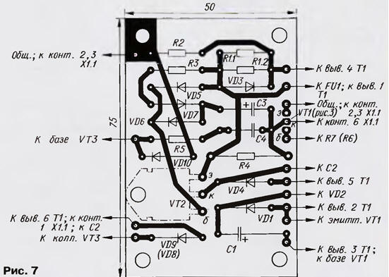
After the voltage at the "K" terminal of the ignition coil passes through zero at the end of the first quarter of the period and exceeds the forward voltage of the VD9 diode, it will open and the "K" terminal through the VD9 diode and the VT3 transistor will be connected to the common wire. A current from the power source will flow through the primary winding of the ignition coil, adding up to the discharge current of capacitor C2 and maintaining the resulting spark discharge (phase 2). Further, the base current of the transistor VT3 becomes so small that the transistor closes, turning off the primary winding of the ignition coil. The resulting surge in voltage at terminal "K" - about 200 V (phase 3 in Fig.) - is sufficient for a second breakdown of the spark gap, since by this moment the spark discharge has not actually been completed yet and the second breakdown occurs in a prepared environment. Further, the discharge proceeds as in a transistor system (phase 4 in Fig. 6). After the breaker contacts are closed, capacitor C4 quickly discharges through resistor R5 and diode VD10, preparing for the next sparking cycle. The total duration of the spark discharge in the improved unit is 2 ms and remains almost constant in the frequency range of the pulse shaper from 10 to 200 Hz at a supply voltage of 14 V. Establishing this block is not difficult. First, they fix it with the transistor VT3 turned off in the same way as described above. Then the transistor VT3 is connected, instead of the constant resistor R5, a variable resistance of 2,2 kOhm is connected and its slider is set to the position of the highest resistance. The power source is turned on and the voltage is set to 14 V. By rotating the variable resistor slider, the shape of the voltage at the “K” terminal of the ignition coil matches that shown in fig. 6 in the frequency range of the pulse shaper from 10 to 200 Hz, after which, instead of a variable resistor, a constant of the corresponding resistance is soldered (usually from 430 to 1000 Ohms). The tests were carried out with the B115 ignition coil for the contact system of the GAZ-24 car with a closed additional resistor. There is no need to be afraid of closing this resistor - the coil will not overheat, since the time of the spark discharge generated by the unit in each cycle is less than the time the coil is under current when the breaker contacts are closed in a conventional ignition system. In the case of using other ignition coils, the optimal capacitance of capacitors C3 and C4 may need to be clarified experimentally. The efficiency of the node on the transistor VT3 is evaluated by turning off the capacitor C4 after adjustment. The sparking frequency is set to 200 Hz and the capacitor C4 is touched at the point where it is turned off - the sound of the spark discharge should change, and the spark cord should become a little thicker, with the formation of a light cloud of ionized gas around it, like a spark discharge generated by transistor systems. There is no danger of damage to the transistor VT3. The VT3 transistor must be installed on the block body, lubricating the surface adjacent to it with KPT-8 paste or Litol-24 grease. If another transistor is used instead of KT898A1 (or BU931ZPF1), an insulating mica gasket will have to be placed under it. Drawing of the printed circuit board of the block according to the scheme of fig. 1 is shown in fig. 7.
The board is designed in such a way as to make it as easy as possible to assemble any variant of the ignition unit described in the article. Resistor R1 for ease of establishment is composed of two - R1.1 and R1.2. Instead of diodes D220, you can use KD521A, KD521V, KD522B; instead of D237V, KD209A-KD209V, KD221V, KD221G, KD226V-KD226D, KD275G are suitable, and instead of KD226V (VD8) - KD226G, KD226D, KD275G. For an octane corrector, a separate fee must be provided. Transformer T1 is assembled on a magnetic circuit Ш16х8. The plates are assembled end-to-end, a strip of fiberglass 0,2 mm thick is inserted into the gap. Winding I contains 50 turns of wire PEV-2 0,55 (it can be thicker - up to 0,8), winding II - 70 turns of wire PEV-2 with a diameter of 0,25 to 0,35 mm, winding III - 420-450 turns of wire PEV-2 with a diameter of 0,14 to 0,25 mm. A photo of one of the variants of the ignition unit (without a casing) is shown in fig. eight.
Literature
Author: E.Adigamov, Tashkent, Uzbekistan
Air trap for insects
01.05.2024 The threat of space debris to the Earth's magnetic field
01.05.2024 Solidification of bulk substances
30.04.2024
▪ Kingston SSDNow E50 Solid State Drives ▪ Identification of a person by blood vessels
▪ section of the site Tools and mechanisms for agriculture. Article selection ▪ article Don't think down the seconds. Popular expression ▪ Article When Was the Computer Built? Detailed answer ▪ article Head of the boiler room. Job description
Home page | Library | Articles | Website map | Site Reviews
www.diagram.com.ua |


 Leave your comment on this article: