|
|


 Arabic
 Bengali
 Chinese
 English
 French
 German
 Hebrew
 Hindi
Hindi Italian
 Japanese
 Korean
 Malay
Malay Polish
 Portuguese
 Spanish
 Turkish
 Ukrainian
 Vietnamese
|
ENCYCLOPEDIA OF RADIO ELECTRONICS AND ELECTRICAL ENGINEERING We install a non-original generator on the Ford Explorer. Encyclopedia of radio electronics and electrical engineering
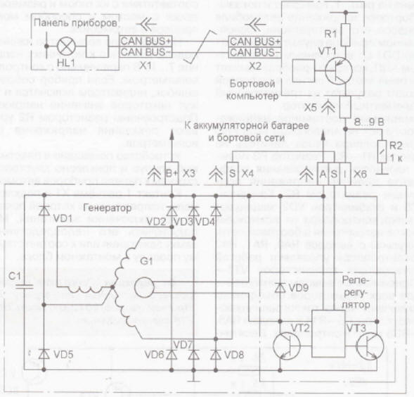
Encyclopedia of radio electronics and electrical engineering / Automobile. Electronic devices Owners of foreign, especially American-made cars are often faced with the fact that original spare parts for their beloved “iron horses” are not available for free sale. Usually they are delivered “to order”, and the owner of the car has to wait several weeks. •If we are talking about the planned replacement of any part or assembly, this is acceptable, but when it is necessary to replace a generator that has suddenly failed, for example, waiting for a new spare part means forced long-term downtime of the car. The solution proposed in the article allows you to install a non-standard generator in a car and ensure its coordination with vehicle control systems.
To determine the input resistance of circuit I, the following experiment was carried out: the three-pin connector X6 is disconnected from the relay regulator, pin S of this connector is connected to the additional terminal of the generator rectifier (pin S of connector X4), pin A is connected with a separate wire to the positive terminal of the battery, pin I connected to pin A through a milliammeter and a 12 V lamp with a power of 1,2 W. With the car engine running, the voltage on the battery was measured (it turned out to be 14,7 V), the current in circuit I (7 mA) and the resistance of the input circuit of the relay regulator was calculated: Rbx = UAb/I, = 14,7/0,007 = 2100 Ohms, of which approximately 100 Ohms is the resistance of the lamp and milliammeter. Based on the above, it has been assumed that circuit I of the relay-regulator and the BC form a voltage divider. And if the voltage at pin I of the X6 connector is 12,1 V when the X6 connector is connected and the voltage in the vehicle’s on-board network is 14,7 V, then it is easy to calculate the output resistance of the BC: Rout = Rin(Uab/Uimeas - 1) = = 2000(14,7/12,1 - 1) = 430 Ohm. The solution circuit is now clear - it is necessary to reduce the resistance of the input circuit I of the relay regulator. In order for the voltage at pin I of the X6 connector to be within 8...9 V, you need to connect an additional resistor in parallel with the input resistance of the relay-regulator (between pin I of the X6 connector and the common water). In the event that the relay-regulator fulfills its control function and closes contact I with transistor VT3 to the common wire, the installed additional resistor will not interfere with the BC’s ability to detect a generator malfunction, since the resistance of circuit I will be close to zero. The total resistance of the parallel-connected additional resistor and the input resistance of the relay-regulator at a voltage at the connection point of 8,5 V (U, nom) should be equal to: Rsum = Rout*Uinom/(Uab - Uinom) = \u430d 8,5 14,7 / (8,5 - 590) \uXNUMXd XNUMX ohms. And the calculated input resistance of the relay regulator is 2 kOhm. This is the reason for the incorrect operation of the bookmaker. Having determined the total resistance, we calculate the resistance of the additional resistor R2: R2 \u2000d Rin * Rsum / (Rin - Rtotal) \u590d 2000-590 / (837- XNUMX) \uXNUMXd XNUMX Ohm. Taking into account the measurement error and rather rough assumptions, I chose an additional 1 kOhm resistor. Let's calculate its power: Рdop \u2d (Uinom) 2 / R8,52 \u1000d 72 / XNUMX \uXNUMXd XNUMX mW. In fact, I installed a 0,25 W resistor on the car. After such modification, when the engine is running, the voltage in the on-board network is 14,7 V, the HL1 warning lamp on the instrument panel does not light up. Which, in fact, was what was required. At the time of publication of the article, the car has been successfully operated for more than 18 months, no shortcomings have been identified. This article contains a certain excess of information, the purpose of which is to explain the principle of the solution. For another American or Japanese car, the voltage at pin I of the relay-regulator connector may be different, but based on a few simple experiments you can determine the required parameters yourself. If the nominal value of this voltage cannot be determined, you can try to replace the constant resistor with a variable resistance of several kilo-ohms - connect one of its terminals to the common wire, and the second - together with the output of the engine to pin I. By rotating the resistor slider, make sure the control lamp goes out. Then the resistance of the variable resistor is measured and a constant one of the closest value is connected instead. And the last recommendation - when working on electrical equipment, do not forget to disconnect the battery. Literature
Artificial leather for touch emulation
15.04.2024 Petgugu Global cat litter
15.04.2024 The attractiveness of caring men
14.04.2024
▪ Seat belt that unfastens in the water ▪ During the holidays, students get stupid ▪ Why was the wheel invented so late ▪ Mobileye EyeQ4 single-chip system for semi-autonomous vehicles
▪ section of the site Data transfer. Article selection ▪ Article Sound in the car. The art of audio ▪ article Why is a collection of songs called an album? Detailed answer ▪ article Communication and radio electrician. Job description ▪ article All-penetrating rings. Focus Secret
Home page | Library | Articles | Website map | Site Reviews
www.diagram.com.ua |

 Leave your comment on this article: