|
|


 Arabic
 Bengali
 Chinese
 English
 French
 German
 Hebrew
 Hindi
Hindi Italian
 Japanese
 Korean
 Malay
Malay Polish
 Portuguese
 Spanish
 Turkish
 Ukrainian
 Vietnamese
|
ENCYCLOPEDIA OF RADIO ELECTRONICS AND ELECTRICAL ENGINEERING Transmission indicator. Encyclopedia of radio electronics and electrical engineering
Encyclopedia of radio electronics and electrical engineering / Automobile. Electronic devices The basis for the development and manufacture of this indicator of the included gear of the car's gearbox was the device described in the article by S. Gulyaev "Indicator of the included gear" ("Radio", 2010, No. 6, p. 41). The fact that such a pointer is useful for both beginners and experienced drivers is said enough in it to make you want to make and install such a device in your car. But the author of the proposed article wanted to improve it by adding some new features. A distinctive feature of the proposed indicator of the included gear is the indication of the inclusion of not only direct gears, but also reverse gear, as well as the parking brake. In addition, in certain cases, arrows are displayed on the indicator, recommending the driver to shift up or down a gear. When a simple sensor for the neutral position of the gear lever is installed in a car, the indicator also signals about it. And when the engine is running, but the car is not moving, the pointer turns into a quasi-analogue tachometer.
The pointer scheme is shown in fig. 1. Since the device I assembled is installed in a VAZ-2110 car, the position numbers of connectors X1 and X2 and the numbers of their contacts correspond to the circuit diagram of the instrument cluster of this car. The pointer is based on the DD1 microcontroller, powered by an internal RC clock generator. Starting its work, the microcontroller program configures the pins of its ports as inputs and outputs in accordance with their purpose in the pointer, disables unused internal modules. Then, the signals of the speed and engine speed sensors, the reversing light switch, the parking brake status contact sensors, the neutral gear and the SA1 calibration mode switch are analyzed cyclically, the presence of the jumper S1 is checked. Based on the results of the analysis of these signals, on the matrix LED indicator HG1, images of symbols are formed that characterize the included transmission and some special situations. Information is displayed on the HG1 indicator in dynamic mode. If an indicator with common LED anodes for each column of the matrix is used, for example TA07-11EWA, jumper S1 should be absent. At the same time, on each of the outputs RB3-RB7 of the microcontroller, the program alternately, at certain intervals, sets the voltage to a high logic level while the level is low on the remaining four outputs. This selects one of the LED columns of the HG1 indicator. Which of the LEDs of the selected column will be turned on determines the code loaded by the microcontroller through the outputs RA0 and RA1 into the shift register DD2. A low level at the output of the register means that the LED of the currently active matrix column connected to it by the cathode is on, and a high level is off. After the set time has elapsed, the program selects the next column and loads the code intended for it into the shift register. Due to the inertia of vision, all the LEDs that form the output symbol appear to be on at the same time. If an indicator with common cathodes of LEDs of each column is used, for example TC07-11EWA, jumper S1 must be installed. In this case, the pulses at the outputs RB3-RB7 and the codes loaded into the shift register DD2 will be programmatically inverted, which is required for the operation of such an indicator.
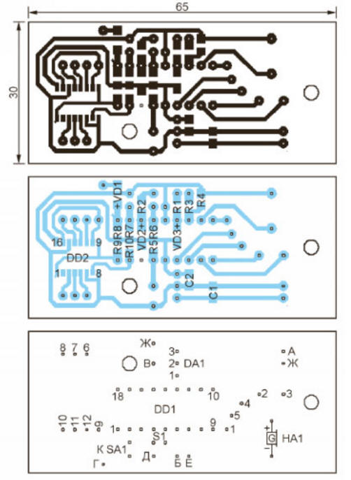
Most of the pointer parts are located on the printed circuit board shown in fig. 2, and the HG1 indicator with quenching resistors R11-R17 - on a separate small printed circuit board shown in fig. 3. The boards are interconnected by a wiring harness, and the numbers of the contact pads to which they are soldered coincide on both boards with the wire numbers according to the diagram in fig. 1. The boards are designed for the installation of resistors and capacitors for surface mounting of size 1206. Diodes VD1-VD3 and shift register DD2 are also in surface mounting packages.
The board with the indicator is placed in a place convenient for the driver to observe its readings. The main board is mounted on racks to the back of the car's instrument cluster or placed in a case of suitable sizes. The connections of the indicator with the instrument cluster are made with pieces of the mounting wire. If the car is stationary and the parking brake is on (a logically low voltage level is set on the cathode of the VD1 diode), the letter P is displayed on the indicator. additionally attracting the attention of the driver. The letter R has priority over P. This means that if the reverse gear and the parking brake are applied at the same time, the letter R will be displayed and the horn will sound. If the parking brake or reverse gear is not engaged and the vehicle is not moving, the indicator turns into a pseudo-analogue tachometer scale. The height of the column of illuminated LEDs is proportional to the engine speed. The pulse signal from the speed sensor is fed to the input RA4 DD1 through the resistor R2 and the protective diode VD2. For each pulse, the contents of the TMR0 register of the microcontroller's internal timer are incremented. As a result, the number of pulses counted by the timer in a certain time is proportional to the crankshaft speed. If the engine is stopped, the column is off. At a rotation frequency of not more than 1000 min-1, its height is one LED, at a frequency of 1000 ... 2000 min-1 - two, at 2000.3000 min-1 - three. And so on up to six LEDs at a frequency of 5000 min-1. If the frequency is more than 5500 min-1, the entire indicator flashes, warning the driver not to increase the frequency further without loading the engine. When the car is moving, a pulse signal from the speed sensor of its movement is fed to the input RB0 DD1 through the resistor R1 and the protective diode VD3. The microcontroller program counts the number of these pulses for the time intervals between TMR0 timer overflows, which are inversely proportional to the crankshaft speed. Therefore, the result of the calculation is proportional to the ratio of the rotation frequencies of the output shaft of the gearbox and the crankshaft of the engine, i.e. with the clutch fully engaged - the gear ratio of the box. Reference values, based on the comparison with which the program makes a conclusion about the included gear (from the first to the fifth), are stored in the EEPROM of the microcontroller. Based on the current engine speed, the program analyzes the correctness of the gear selection. It is recommended to move in first and second gears at a crankshaft speed of no more than 3000 min-1. In third and fourth gears, the permissible frequency is increased to 4000 min-1, and its minimum value in third-fifth gears is taken equal to 1400 min-1. When these limits are exceeded, on the indicator of numbers, the numbers of the included gear are replaced by arrows, suggesting that it is necessary to change the gear and in which direction. After 1,5.2 s, the number of the included gear is displayed again. When the clutch pedal is depressed, the pulse count results may not correspond to any of the available gears. This situation is indicated by the letter C on the indicator. Sometimes the engine stalls while driving. The reasons for this may be different, but in such a situation, the greatest danger is the loss of brake efficiency. The need to start the engine is warned by the letter D on the indicator. Knowing the gear ratios of the gear pairs of the car's gearbox and the characteristics of the sensors of the engine crankshaft speed and speed of movement installed on it, it is possible to calculate in advance the exemplary number of pulses to determine the gear engaged and enter them into the EEPROM of the microcontroller when programming it. But there is another way. Choose a fairly long, straight stretch of road with little traffic. After starting the engine, close switch SA1. The letter K will be displayed on the indicator. Engage first gear and start moving. The microcontroller will count the pulses of the speed sensor and calculate the arithmetic mean of the results of the three measurements. The indicator will display the number of the transfer - the first one. Without stopping the movement, turn on the second gear and wait until its number appears on the indicator. Perform the same operations with the rest of the gears, up to the fifth. After that, the results will be automatically written to the EEPROM. A beep will sound. Open switch SA1. The pointer is ready for use. The shift lever neutral position sensor can be made from a permanent magnet and a reed switch. The magnet is mounted on the lever, and the reed switch is placed nearby so that it is closed by the magnetic field only when the lever is in the neutral position. In this case, the letter N will be displayed on the indicator. The microcontroller program can be downloaded from ftp://ftp.radio.ru/pub/2013/08/indvkp.zip. Author: S. Kashutin
Artificial leather for touch emulation
15.04.2024 Petgugu Global cat litter
15.04.2024 The attractiveness of caring men
14.04.2024
▪ Found a way to influence the development of microbes ▪ Light curtains F3ET and F3EM ▪ New Series of Thick Film Power Resistors ▪ Avian flu in liquid nitrogen
▪ site section Clocks, timers, relays, load switches. Article selection ▪ article Zeus the Thunderer. Popular expression ▪ What are the specific features of the Abbasid Caliphate? Detailed answer ▪ article Types of protection against electric shock ▪ article Canary Trill Simulator. Encyclopedia of radio electronics and electrical engineering ▪ article Phase power regulator. Encyclopedia of radio electronics and electrical engineering
Home page | Library | Articles | Website map | Site Reviews
www.diagram.com.ua |


 Leave your comment on this article: