|
|


 Arabic
 Bengali
 Chinese
 English
 French
 German
 Hebrew
 Hindi
Hindi Italian
 Japanese
 Korean
 Malay
Malay Polish
 Portuguese
 Spanish
 Turkish
 Ukrainian
 Vietnamese
|
ENCYCLOPEDIA OF RADIO ELECTRONICS AND ELECTRICAL ENGINEERING Automatic charger. Encyclopedia of radio electronics and electrical engineering
Encyclopedia of radio electronics and electrical engineering / Automobile. Batteries, chargers The device allows not only charging, but also restoring batteries with sulfated plates due to the use of asymmetric current when charging in the charge (5 A) - discharge (0,5 A) mode for the full period of the mains voltage. The device also provides the ability to speed up the charging process if necessary. Unlike the schemes shown in Fig. 4.2 and 4.3, this device has a number of additional features that contribute to the convenience of their use. So, at the end of the charge, the circuit will automatically disconnect the battery from the charger. And if you try to connect a faulty battery (with a voltage below 7 V) or a battery with the wrong polarity, the circuit will not turn on in charge mode, which will protect the charger and battery from damage. In the event of a short circuit of the X1 (+) and X2 (-) terminals, the FU1 fuse will blow during operation of the device. The electrical circuit (Fig. 4.4) consists of a current stabilizer on a transistor VT1, a control device on a comparator D1, a thyristor VS1 for fixing the state and a key transistor VT2 that controls the operation of the relay K1.
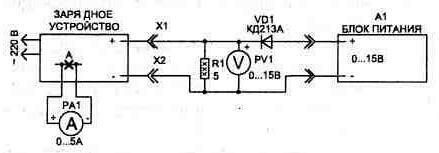
When the device is turned on with the SA1 toggle switch, the HL2 LED will light up, and the circuit will wait until we connect the battery to terminals X1, X2. With the correct polarity of the battery connection, a small current flowing through the VD7 diode and resistors R14, R15 to the VT2 base will be sufficient for the transistor to open and relay K1 to operate. When the relay is turned on, the transistor VT1 starts working in the current stabilizer mode - in this case, the HL1 LED will light up. The stabilization current is set by the resistor values in the VT1 emitter circuit, and the reference voltage for operation is obtained on the HL1 LED and the VD6 diode. The current stabilizer operates on one half-wave of the mains voltage. During the second half-wave diodes VD1, VD2 are closed and the battery is discharged through the resistor R8. The value of R8 is chosen so that the discharge current is 0,5 A. It has been experimentally established that the optimal mode is the charge current of 5 A, the discharge is 0,5 A. While the discharge is in progress, the comparator monitors the voltage on the battery, and if the value of 14,7 V is exceeded (the level is set by setting the resistor R10), it will turn on the thyristor. In this case, the LEDs HL3 and HL2 will start to glow. The thyristor shorts the base of the transistor VT2 through the VD9 diode to a common wire, which will turn off the relay. The relay will not turn on again until the RESET button (SB1) is pressed or the entire circuit is turned off for a while (SA1). For stable operation of the D1 comparator, its power supply is stabilized by the VD5 zener diode. In order for the comparator to compare the voltage on the battery with the threshold voltage (set at input 2) only at the moment when the discharge is made, the threshold voltage by the circuit of the VD3 diode and the resistor R1 rises for the duration of the battery charge, which will prevent its operation. When the battery is discharged, this circuit is not involved in the work. In the manufacture of the design, the transistor VT1 is installed on a radiator with an area of at least 200 square meters. cm. Power circuits from terminals X1, X2 and transformer T1 are made with a wire with a cross section of at least 0,75 square meters. mm. The circuit uses capacitors C1 of the K50-24 type for 63 V, C2 - K53-4A for 20 V, a tuning resistor R10 of the SP5-2 type (multi-turn). fixed resistors R2 ... R4 type C5-16MV, R8 type PEV-15, the rest - type C2-23. Relay K1 is suitable for any, with an operating voltage of 24 V and a permissible current through the contacts of 5 A; toggle switches SA1, SA2 type T1, button SB1 type KM1-1. To adjust the charger, you will need a constant voltage source with a tuning range from 3 to 15 V. It is convenient to use the connection diagram shown in fig. 4.5.
We begin the setting by selecting the value of the resistor R14. To do this, we supply a voltage of 1 V from the power supply A7 and by changing the value of the resistor R14 we achieve that the relay K1 operates at a voltage of at least 7 V. After that, we increase the voltage from the A1 source to 14,7 V and set the comparator threshold with the resistor R10 (to return circuits to its original state after turning on the thyristor, you must press the button SB1). It may also be necessary to select the resistor R1. Lastly, we set up the current stabilizer. To do this, we temporarily install a pointer ammeter with a scale of 1 ... 0 A into the open circuit of the VT5 collector at point "A". By selecting resistor R4, we achieve readings on the ammeter of 1,8 A (for a current amplitude of 5 A), and after that, with SA2 turned on set R4, value 3,6 A (for a current amplitude of 10 A). The difference in the reading of the pointer ammeter and the actual value of the current is due to the fact that the ammeter averages the measured value over the period of the mains voltage, and the charge is made only during half the period. In conclusion, it should be noted that the final adjustment of the stabilizer current is best done on a real battery in steady state - when the transistor VT1 has warmed up and the effect of current growth due to a change in the junction temperature in the transistor is not observed. On this setting can be considered complete. As the battery charges, the voltage on it will gradually increase, and when it reaches a value of 14,7 V, the circuit will automatically turn off the charge circuits. Automation will also turn off the charging process in case of some other unforeseen influences, for example, in the event of a breakdown of VT1 or a power outage. The auto-off mode can also be triggered by poor contact in the circuits from the charger to the battery. In this case, the RESET button (SB1) must be pressed. Publication: radioradar.net
Artificial leather for touch emulation
15.04.2024 Petgugu Global cat litter
15.04.2024 The attractiveness of caring men
14.04.2024
▪ New CC1100 based RF module hit the market ▪ WiFi Mesh System Xiaomi Mesh Router Suits ▪ To predict a heart attack, droplets of blood stop
▪ section of the site Stories from the life of radio amateurs. Selection of articles ▪ article social science. Crib ▪ article Carrying out work at pumping stations. Standard instruction on labor protection ▪ article Crocodile for heat sink. Encyclopedia of radio electronics and electrical engineering ▪ article Guessing the card for a bet. Focus Secret
Home page | Library | Articles | Website map | Site Reviews
www.diagram.com.ua |


 Leave your comment on this article: