|
|


 Arabic
 Bengali
 Chinese
 English
 French
 German
 Hebrew
 Hindi
Hindi Italian
 Japanese
 Korean
 Malay
Malay Polish
 Portuguese
 Spanish
 Turkish
 Ukrainian
 Vietnamese
|
ENCYCLOPEDIA OF RADIO ELECTRONICS AND ELECTRICAL ENGINEERING Power amplifier on a GU-81M lamp. Encyclopedia of radio electronics and electrical engineering
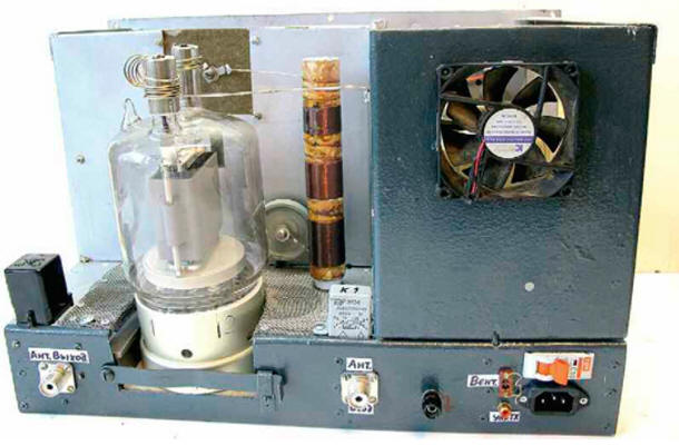
Encyclopedia of radio electronics and electrical engineering / Tube Power Amplifiers The power amplifier (PA) is made according to the scheme with a common grid on a time-tested reliable direct filament lamp with graphite anodes GU-81M (Fig. 1). The undoubted advantages of this PA are its readiness for operation in a few seconds after switching on and unpretentiousness in operation. The protection against overloads and short circuits used in the amplifier, soft switching on and adjustable sleep mode of operation made it possible to create an economical PA with decent characteristics at minimal dimensions and costs. It uses mainly domestic components. The amplifier has a low level of acoustic noise, since the fan turns on automatically (only when the temperature in the lamp compartment reaches more than 100 оFROM). High linearity is ensured by the choice of the optimal operating mode of the lamp and the use of a variometer in the P-loop instead of the traditional coil with shorted turns. All this made it possible to obtain suppression of the second and third harmonics in the output signal at a level of -55 dB. The output power of the amplifier is 1 kW at a lamp anode voltage of 3 kV and an input power rating of 100 watts.
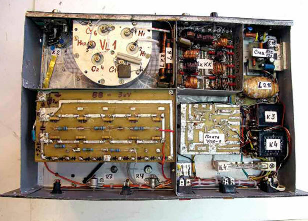
At the input of the amplifier, range P-circuits L9-L17, C8-C25 are switched on, switched by relay K6-K14. They provide coordination with any imported transceiver (even without a built-in tuner), providing an input SWR of at least 1,5 on all bands. The transition time of the PA to sleep mode from 5 s to 15 min is set by the regulator, which is displayed on the front panel. The amplifier operation mode has also been introduced with a reduced output power of up to 50% ("TUNE"), which is obtained by reducing the lamp voltage VL1 to 9 V. At the same time, you can tune the PA for an arbitrarily long time and fully, without loss of signal quality, work on the air. The amplifier uses a parallel power supply circuit for the anode circuit. Compared to the serial circuit, it is safer, since there is no high voltage on the elements of the P-loop. The use of a high-quality inductor connected in parallel with the variometer windings on the HF bands, and the absence of shorted turns of the P-loop coil also made it possible to obtain almost the same output power on all ranges. When the PA is connected to the network, a voltage of 220 V is supplied through the L19L20 mains filter to the primary winding of the T2 transformer through the EL1 halogen lamp. This provides a soft start of the amplifier, extending the life of the GU-81M lamp and other elements of the device. After charging the capacitors C40-C49 of the high-voltage rectifier up to 2,5 kV, the voltage taken from the divider on resistors R13-R16 is fed to the base of the transistor VT3, the transistor opens, relay K4 is activated, closing its contacts K4.1, K4.3, K4.4. 1 halogen lamp EL2. The full voltage of the network is supplied to the winding I of the transformer T4. The peculiarity of this inclusion is the small hysteresis of the operation / release of the K2 relay, which provides reliable protection against various overloads (short circuit in the secondary power circuits, filament circuit and short circuits in the winding of the transformer T3). If any of the above faults occurs, the voltage at the base of the transistor VT4 will decrease, the relay K2 will turn off and the transformer T1 will again be connected to the network through the EL1 lamp, which limits the current to 1 A, preventing failure of the VLXNUMX lamp and the PA as a whole. The operation of the amplifier is controlled by a node on the transistor VT1. When contact X1 "Control TX" is shorted to a common wire (the current in this circuit is 10 mA), the transistor opens and relays K1, K2 connect the input and output of the amplifier to the RF connectors XW1, XW2 with their contacts. At the same time, the contacts of relay K1.2 close the cathode circuit of the VL1 lamp to a common wire, and the amplifier switches to signal transmission mode. In the "QRP" mode, the SA3 switch turns off the power to the transistor VT1, which prevents the amplifier from switching to the active mode, and the antenna receives a signal directly from the output of the transceiver. Fans M1 and M2 maintain the temperature of the PA, which excludes overheating of the amplifier elements. With a reduced supply voltage, they operate almost silently. The power supply compartment of the amplifier is equipped with an M1 computer fan (12 V, 0,12 A, diameter 80 mm), operating at a voltage of 7 ... filament lamp circuit VL8. In normal mode, the fan operates at a supply voltage reduced to 2 ... 150 V, and at full output power it rises to 150 ... 37 V. The node on the VT24 transistor controls the operation of the M1 fan. When the amplifier switches to the "TX" mode, the +8 V voltage from the collector of the transistor VT10 through the diode VD20 and the resistor R22 will go to the capacitor C2. When the temperature in the lamp compartment rises to 100 оC, the thermal contacts SK1 open and after 8 ... 10 s the capacitor C35 is fully charged. Transistor VT2 will open, relay K5 will work and switch fan M2 to higher speeds. After the amplifier exits the active mode, due to the slow discharge of the capacitor C35 through the base circuit, the transistor VT2 is held open for another 1,5 ... 2 minutes and the fan continues to operate at high speeds. If the transfer time is less than 8 s, the fan runs at a lower speed without creating unnecessary acoustic noise. Resistor R34 is selected according to the minimum fan speed, which ensures the temperature regime in the PA. The power-saving mode is used in the amplifier, which has proven itself in many of the author's designs. The control unit for this mode is made on transistors VT4-VT6. When the amplifier is powered on, capacitor C55 is charged from a + 12 V source (DA1) through a trimmer resistor R9 and resistor R12. Each time you turn on the transmission from the collector of the transistor VT1, a voltage of +24 V is supplied to the base of the transistor VT4 through a divider on resistors R6, R7. Transistor VT4 opens and discharges capacitor C55. But if the amplifier has not been transmitting for some time, the capacitor C55 has time to fully charge (the charging time is determined by the resistor R9), the composite transistor VT5, VT6 opens and closes the base circuit of the transistor VT13 to a common wire. Relay K4 is de-energized, and the primary winding of transformer T2 is re-energized through the lamp EL1. The amplifier will switch to power-saving mode, in which the current consumption and heating are minimal, and the amplifier is ready to operate at full power in 1,5 ... 2 s. In standby mode, the filament voltage of the VL1 lamp is reduced to 9 V. To exit this mode, it is enough to briefly press the SB1 "TX" button or put the transceiver into transmission mode by connecting the X1 connector to a common wire. Voltage stabilizers on DA1 and DA2 chips are used to power automation units and relays. Resistor R31 limits the current in case of a short circuit in the +24 V circuit. The high-voltage rectifier is built according to a voltage doubling scheme, which is close in its characteristics to a bridge circuit, but requires half the number of turns of the anode winding of the transformer. Transformer T1 is made on a magnetic circuit of size K20x10x7 mm from ferrite grade 200-400NN. The secondary winding contains 27 turns of PELSHO 0,25 wire. The primary winding is a wire passing through the hole of the ring and connecting the relay contact K2.1 with the variometer L1. The network transformer T2 is wound on a toroidal magnetic circuit from LATR-1M (9 A). If the PA is operated in a "moderate" mode (i.e., without prolonged operation in contests), you can leave the "native" network winding, which contains 245 turns of wire with a diameter of 1,2 mm. If the winding is rewound, it is desirable to increase the wire diameter to 1,5 mm. The no-load current of the network winding should be 0,3 ... The relay power winding (III) contains 0,4 turns of PEV-1300 2 wire, the filament (IV) - 0,7 turns of PEV-28 2 wire with a tap from the 0,7th turn. The amplifier is mounted in a metal case measuring 500x300x300 mm. Chassis basement depth - 70 mm (Fig. 2). In the basement (Fig. 3) there are boards for a high-voltage rectifier, control, voltage stabilizers +12 and +24 V, a power meter board, a surge protector, an input circuit board, a K3-K5 relay, an SF1 VA47-29 circuit breaker for a current of 10 A. The EL1 lamp is located near the SA4 "PWR" switch so that its glow can be seen through the transparent housing of the HL1 LED (blue color of the glow), which is installed on the front panel next to SA4.
The SA1 switch was used from the matching device of the R-130 radio station, which has undergone significant modernization: the latch has been redesigned into ten positions, a biscuit has been added for switching the relay of the input circuits, and a common silver-plated current collector 1,5 mm thick has been added. Variometer L1 - from the R-836 radio station. It has switchable windings and its inductance varies from 2 to 27 uH. You can use the variometer from the R-140 or R-118 radio station, but they have somewhat larger dimensions. Coil L2 is wound with a copper tube 6 mm in diameter on a mandrel 60 mm in diameter. It has nine turns with taps from the 3rd, 5th and 7th turns, counting from the top (see Fig. 1) coil output. Choke L3 is wound with wire PEV-2 0,25 on a ceramic rod with a diameter of 8 mm and consists of four sections of 100 turns. Winding - type "universal", inductance - about 200 μH. The antiparasitic inductor L4 is made of steel carbon spring wire with a diameter of 1,3 mm and contains 5 ... 7 turns wound on a mandrel with a diameter of 12 mm. From the same wire (without cutting it), as a continuation of the inductor, a spiral spring contact is made - 7 ... 8 turns on a mandrel with a diameter of 18 mm, tightly put on the lamp anode terminal. The winding of the anode choke L5 is three-section - 100, 80 and 60 turns of wire PEV-2 0,35. The winding is made turn to turn (between sections 1,5-2 turns) on a ceramic frame from a PEV-100 resistor. Distance between sections - 15 mm. After winding, the turns are impregnated with BF2 glue or ML92 varnish. Choke L6 contains 50 turns of PEV-2 0,7 wire, wound turn to turn on a rod with a diameter of 10 and a length of 80 mm from 1000NN ferrite. A two-winding inductor L7, L8 contains 2x27 turns of PEV-2 1,8 wire wound bifilar turn to turn on two core magnetic cores 10 in diameter and 100 mm long made of 600NN ferrite. Coils L9-L17 are frameless, wound with PEV-2 wire on a mandrel with a diameter of 18 mm. All parts of the input circuits are soldered from the side of the printed conductors on the relay board. The winding data of the coils and the ratings of the capacitances of the capacitors are given in the table. Table
Inductor L18 - DM-2,4 with an inductance of 10 μH. The L19L20 line filter is wound on half of the magnetic circuit from the TVS90 or TVS110 transformer. Winding - bifilar wire MGTF 1 mm before filling. Thermal contact SK1 (from an electric cooler or other heating device) with normally closed contacts is designed for a response temperature of 90 ... 100 оC. It is installed on the GU-81M lamp panel. The GU-81M lamp is installed in the native "horseshoe" panel 30 mm below the chassis level. The widespread opinion about the need to "undress" the GU-81M will bring nothing but problems with broken contacts, complicating the lamp mounting and cooling. A "significant", according to some radio amateurs - designers, a decrease in the anode-cathode capacitance, which amounted to 2,8 ... 3 pF (tested experimentally), will not have a significant effect on the operation of the PA. On the front panel of the PA there are controls, indication and control (Fig. 4). Measuring instruments PA1 and PA2 - М42300. PA1 has a total deflection current of 1 mA, while PA2 can have it much more. This device must measure (taking into account the shunt R30) current up to 1 A. The scale of the pA1 device is calibrated directly in watts. The VL2 indicator is an imported neon lamp for a voltage of 220 V. The EL1 lamp is a halogen lamp, 150 W at 220 V (diameter 8 and length 78 mm).
On the rear panel of the amplifier there are RF connectors, control socket X1 "tulip", ground terminal, network connector and fan connector. All RF connectors, capacitor C3, ground terminal, blocking capacitors and terminal 6 of the GU-81M lamp panel are interconnected by a copper bus with a cross section of 15x0,5 mm. Relay K1 - REN33, K2 - REN34, K3 - TKE54, K4 - TKE56, K6-K14 - RES9 (passport RS4.524.200). All relays are for rated operating voltage 24-27 V. Variable capacitor C3 - with a gap of 0,8 ... 1 mm, capacitors C4-C7, C27 - K15U-1, C33 - KVI-3. Oxide capacitors C40-C49 are imported, capacitors C35 and C55 must have a low leakage current. All blocking capacitors - KSO, C8-C25 - KT, KSO. All fixed resistors (except R3) are of the MLT type, R3 are of the SQP-5 series. The primary adjustment of the amplifier is carried out with the winding II of the transformer T2 turned off. They measure the filament voltage, the voltage at the outputs of the stabilizers, debug the operation of the automation units, and only after making sure that these units are fully operational, they move on to high-voltage circuits. Instead of a high-voltage winding, any low-power transformer is connected to the doubler rectifier and, by supplying an alternating voltage of 100 ... If everything is in order, connect, observing the precautionary measures, the high-voltage winding. The unloaded rectifier voltage can reach 200 V. The quiescent current of the VL1 lamp should be 25 ... 30 mA. Without connecting the transceiver, check the PA for the absence of self-excitation in the "TX" mode on all ranges. Further, by connecting the transceiver with a cable no longer than 1,2 m, with the tuner turned off (if any), the input circuits L9-L17, C8-C25 are tuned with the PA switched on for transmission, applying a 10 ... 15 W signal to its input. The adjustment is made, starting from the HF ranges, according to the minimum SWR on the transceiver device. Then the input power is increased and by shifting / expanding the turns of these coils, the setting is refined again. The P-loop is also tuned at a minimum input power, having previously connected a load equivalent of 50 ohms of sufficient power to the amplifier output (for example, from the R-140 radio station), and starting from the HF bands, select the position of the taps at the L2 coil. Then move on to the low bands. The suppression of harmonics, measured by the author using the S4-25 spectrum analyzer and the imported 8590A analyzer, was at least -45 dB on the 28 MHz band and -55 dB on the low bands. The anode of the GU-81M lamp during long-term (3 ... 5 min) operation in CW mode had a slightly pink tint, which is quite acceptable for a lamp. Author: Vyacheslav Fedorchenko (RZ3TI)
Machine for thinning flowers in gardens
02.05.2024 Advanced Infrared Microscope
02.05.2024 Air trap for insects
01.05.2024
▪ Smoking mother harms unborn child
▪ site section Electric motors. Article selection ▪ article Now everything will be like with grandma. Popular expression ▪ article Where are babies named after the day of the week they are born? Detailed answer ▪ article Car Laguna. Personal transport ▪ article Portable welding machine. Encyclopedia of radio electronics and electrical engineering ▪ article Loop does not grab the finger. Focus Secret
Home page | Library | Articles | Website map | Site Reviews
www.diagram.com.ua |


 Leave your comment on this article: