|
|


 Arabic
 Bengali
 Chinese
 English
 French
 German
 Hebrew
 Hindi
Hindi Italian
 Japanese
 Korean
 Malay
Malay Polish
 Portuguese
 Spanish
 Turkish
 Ukrainian
 Vietnamese
|
ENCYCLOPEDIA OF RADIO ELECTRONICS AND ELECTRICAL ENGINEERING Amplifier for self-powered stereo telephones. Encyclopedia of radio electronics and electrical engineering
Encyclopedia of radio electronics and electrical engineering / Transistor power amplifiers Most digital mobile media devices have a low output level on the stereo headphone jack pins. Typically, the maximum output signal swing when playing music files does not exceed 1 V, and when playing videos and listening to radio performances, it is often reduced by 3 ... 10 times. At the same time, if in a quiet environment, when using low-impedance phones, you can still make out something, then, for example, in a noisy room or on a train, the background noise may turn out to be louder than the sound from the headphones. To listen to multimedia files in different environments with optimal volume, you can use the self-powered UMZCH described below, which is connected between the signal source and stereo phones. Devices that can be used as UMZCH for stereo phones have already been described in the magazine [1,2], but they require connection to a mains voltage source. The proposed stereo UMZCH is specially designed to work on head phones and is powered by a built-in high-capacity rechargeable battery, which ensures its long-term operation. The amplifier circuit is shown in fig. 1. The input plug of the XP1 device is connected to the AF signal source. Through the RC filters R1C3 and R3C4, the stereo signal is fed to the volume control - a dual variable resistor R6. Capacitor C2 allows you to connect the UMZCH and the signal source to one common DC power source, for example, described in [3]. In this case, minor periodic "digital" noise may appear in phones - if the common output wire at the stereo signal source is not a power minus.
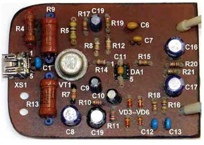
From the engines of the sections of the variable resistor, the stereo signal through the coupling capacitors C6 and C7 is fed to the non-inverting inputs of the op-amp of the DA1 microcircuit. The voltage gain in the channels depends on the ratio of the resistance values of the resistors R14/R10 and R15/R11. In this device, the gain is chosen relatively large, which almost always makes it possible to raise the sound level to the optimum, but such a solution required the use of low-noise op-amps. Damping circuits R18C12 and R16C13 prevent possible self-excitation of the op-amp at ultrasonic frequencies. Diodes VD3-VD6 protect the microcircuit from static electricity discharges and from damage by leakage currents of mains power supplies. The amplified stereo signal is fed through coupling capacitors C15-C18 to the XS2 jack, to which stereo headphones are connected. Resistors R20, R21 prevent an unpleasant click when connecting phones to a working amplifier. The operating mode of the op-amp DA1.1 and DA1.2 sets the resistive voltage divider R19R17. The maximum voltage swing at the UMZCH output is about 3,9 V at a microcircuit supply voltage of 4,2 V. The UMZCH is powered by a battery of parallel-connected lithium-ion batteries G1 and G2. It is connected to the amplifier nodes through the A1 charge/discharge controller. A polymer resettable fuse FU1 is installed between it and the battery. To charge the battery, a voltage source of 1 ... 4,8 V is connected to the XS6,5 socket. The charging current is limited by resistors R9, R13 connected in series, Schottky diodes VD1, VD2, the resistance of the connecting wire and the output resistance of the charger. When the battery charging current flows through the circuit, the germanium transistor VT1 is open and the HL1 LED is lit. Diode VD1 limits the rise in voltage at the terminals of the resistor R4. Capacitor C5 reduces the sensitivity of transistor VT1 to power supply ripple. Capacitor C8 ensures correct operation of controller A1. The use of two series-connected resistors R9, R13 instead of one larger dissipation power allows you to more evenly distribute the heat in the device case. When during the charging process the voltage at the battery terminals reaches 4,22...4,25 V, the controller A1 disconnects the batteries G1, G2 from the charging circuit. Since the charger current can be obviously greater than the current consumed by the DA1 chip from the power source, when the battery is turned off by the controller A1, the DA1 supply voltage rises to 4,6 ... 6,3 V, which has a positive effect on increasing the maximum voltage swing at the UMZCH outputs . The supply voltage to DA1 is supplied through the closed contacts of the switch SB1, the HL2 LED lights up when the UMZCH is running. To reduce the current consumed by this indicator, a super-bright LED is used as HL2, which glows quite brightly at a current of about 150 μA. Most of the parts are mounted on a 66x49 mm circuit board (Fig. 2), mounting is low-profile, double-sided, hinged. After checking the operability of the device, the board must be covered on both sides with a thick layer of zaponlak (make sure that it does not get into the sockets of the sockets of the connectors, into the variable resistor and the power switch).
The APA2308 is a dual high quality low noise op amp specifically designed for use as an AF amplifier for stereo headphones. The microcircuit with the J index is produced in the DIP-8 package, with the K index - SOP-8. You can use the TL3414A chip (the pin assignment is the same as that of APA2z08). If such microcircuits are not commercially available, you can try to find them in old computer devices for reading / writing CDs. Instead of the germanium transistor MP25A, you can use any low-frequency germanium from the MP25, MP26, GT402 series (case variant - 2), as well as foreign GT2307, SFT307, SFT352; instead of Schottky diodes MBRD320 - MBRD330, MBRD340, MBRD835, 1N5820, 1 N5821, MBR320, MBR330, 15MQ040N, 30BQ040, and instead of 1N914 diodes - any of 1 N4148, PMLL4148, PMLL4448, 1 SS176, KD510A, as well as KD521, KD522 with any letter index. To control the volume, a high-quality dual variable resistor from the imported SANIO M-977DSR music center is used, its "cold" leads are electrically connected together inside the case. You can use any similar dual resistor with a resistance of 10 ... 150 kOhm (the smaller it is, the better). All signal wires connected to the volume control must be shielded, the metal shield is connected to a common wire. The remaining resistors are S2-14, S2-23, MLT, OMLT, RPM or imported analogues. Under the resistors R9, R13, additional ventilation holes are drilled in the circuit board. Resistors R1, R3 and capacitors C3, C4 are soldered to the corresponding terminals of the sections of the dual variable resistor R6, resistor R22 - to the contacts of the switch SB1. Non-polar capacitors - small-sized ceramic, for example, K10-50 or analogues (those that are installed in signal circuits must be checked for the absence of a microphone effect, for this reason capacitors K10-7 cannot be installed). The rest of the capacitors are imported oxide ones with a height of 4 ... 6 mm. LED RL36-SR114S (red glow with a lens diameter of 3 mm) can be replaced by any of the series KIPD66, RL30N, L-934S. Instead of the RL30-CB744D LED (blue glow), you can use, for example, RL50-CB744D, RL30-WH744D. When mounting the HL2, keep in mind that not all ultra-bright LEDs contain protective zener diodes, so be sure to protect them from static electricity during installation by connecting the terminals with a temporarily installed jumper wire. The SB1 switch is an imported small-sized push-button, the group contacts of the same name are connected in parallel. Socket XS1 - miniUSB, this allows you to use most chargers from mobile multimedia devices and PC system units to charge the battery. You can also install a microUSB socket, which is the standard for modern mobile communication devices, but these sockets have poor reliability. Controller A1 is removed from a defective Samsung Lithium Ion phone battery (Figure 3). He "knows how" to disconnect the battery from the circuit, not only when fully charged, but also when it is discharged to the minimum allowable level, which not all controllers of a similar purpose are capable of.
Since there is no data on the presence of a protective fuse, a polymer self-resetting fuse for a current of 1,1 A is installed between the controller and the battery (any low-voltage fuse for a current of 1,1 ... 1,85 A is suitable). The steel contact petals of the controller are soldered with acetylsalicylic acid flux. A fuse is soldered to the negative terminal, and the corresponding wire from the battery is connected to the positive terminal. Before starting operation, check the controller for proper operation. Japan-made Panasonic-Matsushita CGR18650C lithium-ion batteries removed from a 2004 laptop battery. Previously, they were fully charged, measured after eight months, the total capacity of the batteries when discharging with a current of 1 A was about 4500 mAh, which indicates their very high quality. It should be noted here that among the 18650 batteries sold at retail, there are many low-quality and fake copies (with a high self-discharge current, several times less capacity than on the label, with a short service / storage life). Fakes, according to the author, are all 18650 batteries with a declared capacity of more than 3000 mAh. When mounting such batteries, be extremely careful - in the event of a short circuit, the current in the circuit can reach several tens of amperes. The wires are soldered to steel petals welded to the battery case. They are glued to the body of the device with double-sided adhesive tape. Amplifier housing - plastic, dimensions 88x57x35 mm. Ethylene vinyl acetate glue, as well as Quintol and BF-2 are used to fasten the elements in it. For better adhesion, it is recommended to roughen the plastic surfaces to be bonded with a fast-rotating drill or cutter. In the lower part of the case, sticky aluminum foil is glued as a screen, electrically connected to a common wire, the connection point is the screen of the variable resistor R6. A view of the layout of nodes in the housing is shown in fig. 4, the appearance of the amplifier - in fig. 5.
Accurately made from serviceable parts, the device starts working immediately and does not require adjustment. With a supply voltage of 4,2 V in the absence of a signal, the UMZCH consumes a current of about 2,8 mA, when working with phones with a resistance of 32 ohms at the maximum (optimal) volume - about 18 mA, thus, a full charge of the battery will last more than 250 hours continuous operation of the device. The charging time of a completely discharged battery depends on its actual capacity and the features of the charger (when charging from a power supply unit similar to that described in [3], it is about a day). Literature
Author: A. Butov
Machine for thinning flowers in gardens
02.05.2024 Advanced Infrared Microscope
02.05.2024 Air trap for insects
01.05.2024
▪ Rare earth materials from wastewater ▪ Samsung's New LM281D+ Series LEDs ▪ LCD monitors and TVs are getting cheaper ▪ Long-lasting battery with liquid electrodes ▪ Samsung 8Gb DDR4 chips and 32GB DDR4 modules
▪ section of the site Encyclopedia of radio electronics and electrical engineering. Article selection ▪ article Wet chicken. Popular expression ▪ Article How long can a person live? Detailed answer ▪ Recruiter article. Job description ▪ article Application of solar modules. Encyclopedia of radio electronics and electrical engineering
Home page | Library | Articles | Website map | Site Reviews
www.diagram.com.ua |


 Leave your comment on this article: