|
|
ENCYCLOPEDIA OF RADIO ELECTRONICS AND ELECTRICAL ENGINEERING Power amplifier on bipolar transistors. Encyclopedia of radio electronics and electrical engineering
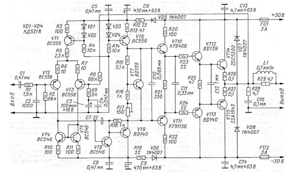
Encyclopedia of radio electronics and electrical engineering / Transistor power amplifiers The proposed amplifier has a low level of non-linear distortion and is capable of providing a nominal power of up to 70 W in a load with a resistance of 4 ohms. The author abandoned the electronic protection of powerful transistors and speakers, limiting himself to the inclusion of fusible links in the power circuit, in order to exclude the possible operation of protection on a complex load. However, to increase reliability and power, the board provides for the placement of elements for an additional pair of powerful transistors. Many people know how difficult it can be to choose a power amplifier circuit among a wide variety. The UMZCH offered here was developed for a wide range of radio amateurs, has noteworthy technical characteristics and provides natural and detailed sound. It is relatively easy to assemble and set up, undemanding to details, stable and reliable. The diagram of one channel of the power amplifier is shown in fig. 1. The parameters below are measured using a stabilized power supply. Technical specifications
The input signal through the high-pass filter C1R2 and low-pass filter R1C2 is fed to the differential stage on transistors VT2, VT3, in the emitter circuit of which a stable current source is connected to the transistor VT1. In the collector circuits of the cascade, a current mirror on transistors VT4, VT5 is used. Next, the signal follows a voltage amplifier (VU) on a VT8 transistor with a buffer load in the form of an emitter follower on a VT9 transistor. The buffer in this case allows you to unload the UN and introduce a compensation OS, which reduces nonlinear distortions. Further, the voltage amplified signal is fed to the output stage. The output stage, assembled on transistors VT10-VT15, is a three-stage emitter follower. Transistor VT7 sets its quiescent current and performs offset thermal compensation for powerful transistors. Transistor VT6 is a source of stable current for the emitter follower and bias circuit on VT7. The R28C15 circuit protects the UMZCH from self-excitation at high frequencies. The L1R29 circuit increases the stability of the amplifier with a capacitive load. Diodes VD7, VD8 protect the output transistors from reverse polarity voltage, and resistors R26, R27 increase the thermal stability of the mode. Capacitor C7 is phase-correcting, it ensures the stability of the amplifier when it is covered by its total feedback (OOS). The following parts can be used in the amplifier. Resistors R26, R27 - ceramic with a power of 5 W, R28, R29 - MLT-1, the rest - MLT-0,125 or MLT-0,25. Resistors R6, R7, R10, R11 should be selected with a deviation of no more than ±2%. Capacitors C1, C5, C8, C11-C14 - K73-17; C4, C10, C15 - KM-5, KM-6 or K10-47; C2, C7 - ceramic with normalized TKE, for example, groups M75-M750. Diodes KD521V can be replaced with 1N4148. Possible replacements for transistors: BD139 - for KT817G; BD140 - on KT816G. Powerful transistors 2SC5200, 2SA1943 are interchangeable with KT8101, KT8102; in extreme cases, it is possible to use KT819GM, KT818GM. Coil L1 - single-layer, with an inner diameter of 10 mm, contains 8 turns of any copper wire in varnish insulation with a copper diameter of 0,7 mm.
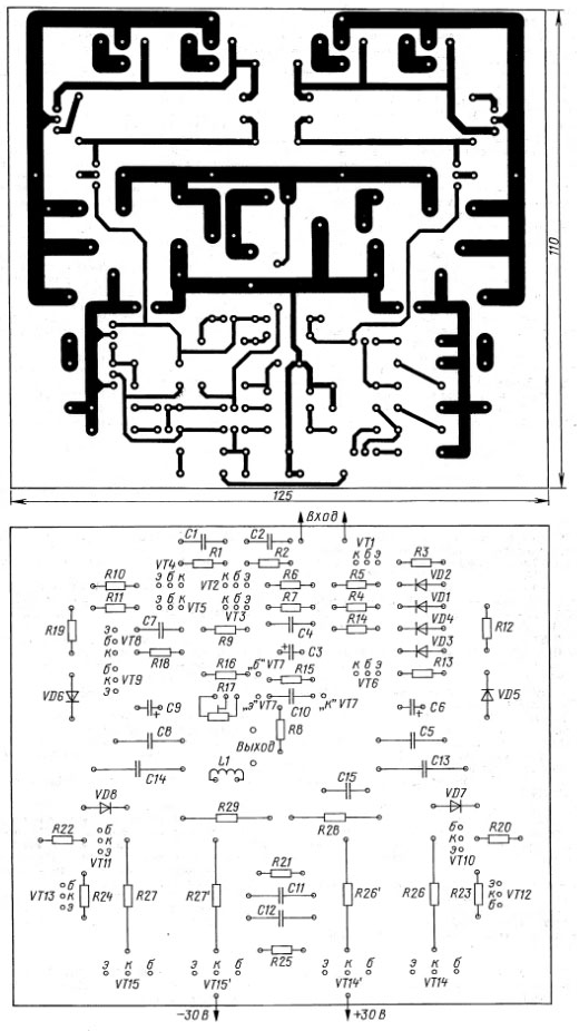
The amplifier is assembled on a printed circuit board measuring 125x110 mm. One of its variants is shown in Fig. 2a, and the corresponding arrangement of parts is shown in Fig. 2,6. The board provides space for the second pair of output transistors. This may be necessary, for example, when increasing the output power or when using less powerful transistors. In general, the amplifier does not require special installation, you just need to follow the well-known rules. Wires for connecting the power supply and load with a cross section of at least 2,5 mm2 must be twisted along the entire length with a pitch of 10 ... 15 mm, they are mounted without bundles. The amplifier input is connected with a shielded wire. Powerful transistors are mounted on a heat sink with a surface area of about 800 cm2 (per channel) through mica spacers. Use thermal paste to increase thermal conductivity. Transistors VT12, VT13 also need to be installed with small heat sinks with an area of 10 ... 15 cm2. Transistor VT7, used as a temperature-dependent bias voltage source, should be placed next to the case of one of the powerful transistors and have good thermal contact with it. It is desirable to mount the amplifier on a non-magnetic metal chassis connected to a common wire at one point. After checking the correct installation, the input of the amplifier is short-circuited, the engine of the tuning resistor R17 is set to the upper position according to the diagram, and an oscilloscope is connected to the output. Instead of fuses (fuses), current-limiting resistors with a power of 1 ... 2 W with a resistance of 30 ... 50 Ohms are soldered. After applying power, check the absence of a constant voltage at the output of the amplifier (permissible value of ± 15 mV) and the absence of self-excitation. Next, the protective resistors are soldered and fuse-links are installed in their places. Then, with a trimmer resistor R17, the quiescent current of the output transistors is adjusted to 100 mA, guided by the voltage drop across resistors R26, R27, equal to 20 mV. After warming up the amplifier for 10 minutes, adjust the quiescent current. On this, the adjustment can be considered complete. When choosing a PSU, it should be borne in mind that the pulse converter in the unit, although it has smaller dimensions and weight, is a strong source of interference in a wide frequency band, the fight against which is not always justified. Therefore, it is often preferable to use a conventional mains transformer with a rectifier. The transformer must have a power of at least 150 W per channel, this contributes to a smaller "drawdown" of the supply voltage at the maximum power of the amplifier. Diodes must be designed for direct current of at least 10 A, for example, KD2999A, KD2999B. They have a low forward voltage drop, which reduces heat dissipation and increases the efficiency of the power supply as a whole. If desired, this amplifier can be equipped with current protection for output transistors, for example, described in the article by P. Zuev "Amplifier with multi-loop feedback" ("Radio", 1984, No. 11, pp. 29-32; No. 12, pp. 42, 43) . Author: V. Grechishkin
Machine for thinning flowers in gardens
02.05.2024 Advanced Infrared Microscope
02.05.2024 Air trap for insects
01.05.2024
▪ Electronic innovations in service in Iraq ▪ Alternate Reality for Scouts
▪ section of the site History of technology, technology, objects around us. Article selection ▪ article Artificial human organs. History of invention and production ▪ article Which Russian river carries water to two oceans at once? Detailed answer ▪ article Reducer for a snowmobile. Personal transport ▪ article car. Security devices and alarms. Directory
Home page | Library | Articles | Website map | Site Reviews www.diagram.com.ua |


 Arabic
 Bengali
 Chinese
 English
 French
 German
 Hebrew
 Hindi
Hindi Italian
 Japanese
 Korean
 Malay
Malay Polish
 Portuguese
 Spanish
 Turkish
 Ukrainian
 Vietnamese


 Leave your comment on this article: