|
|


 Arabic
 Bengali
 Chinese
 English
 French
 German
 Hebrew
 Hindi
Hindi Italian
 Japanese
 Korean
 Malay
Malay Polish
 Portuguese
 Spanish
 Turkish
 Ukrainian
 Vietnamese
|
ENCYCLOPEDIA OF RADIO ELECTRONICS AND ELECTRICAL ENGINEERING Application of electro-acoustic feedback in active speakers. Encyclopedia of radio electronics and electrical engineering
Encyclopedia of radio electronics and electrical engineering / Speakers In the article, the author considers the types of feedback covering the power amplifier, which also takes into account some properties of the acoustic system emitters, correcting to a certain extent the shortcomings of the speakers. Electro-acoustic feedback (EAOS) most effectively reduces various distortions in the low-frequency band, however, the applicability of this technology is limited only in speakers with built-in UMZCH. The author proposes a brief methodology for calculating such an AU and a diagram of additional electronic components. Note that the author has repeatedly presented his active speakers at exhibitions (with built-in UMZCH and EAOS). They differ in realism of sounding and special purity in the bass register, where EAOS operates. Among the main problems of high-quality sound reproduction (SV) in the LF band through acoustic systems (AS) with electrodynamic heads (EDG), two main ones can be distinguished: distortion of the frequency response and phase response, as well as a large amount of non-linear distortion (NI), especially at low frequencies. The reasons for the first of these are compromises in the choice of loudspeakers, their acoustic design (AO), as well as the acoustic properties of the listening room (KdP) and the placement of speakers in it. The result of this type of distortion is transient response (TR) distortion, which results in distortion of the audio signal's envelope, especially with sudden level changes, commonly characterized as "blur", "hum" and "bass lag" effects. The main reason for the second problem is the need for a significant increase in the displacement (stroke) of the EDG cone, which is especially emphasized when it is not sufficiently rigid and leads to the appearance of additional overtones. Methods for reducing distortion in speakers Below, we briefly consider the possibilities of using various methods to overcome or reduce these problems in the most common types of speakers with AO in the form of a phase inverter (FI) and a closed box (CL), but without taking into account the influence of the KdP acoustics and the location of the speaker in it. AS with AO in the form of FI, if implemented correctly, can significantly expand the frequency response in the region of the lower cutoff frequency in the SV band, as well as reduce NI and, which is especially important, with relatively small volumes of AS, compared with AS in the form of CL. However, all these advantages are accompanied by significant distortions of the RP, which are often the main criteria for assessing the quality of pollutants, of course, taking into account the given functional purpose of the AU. An AS with AO in the form of a WA has a much better RP, however, this requires a significant increase in the volumes of the AS with a decrease in the lower cutoff frequency in the SV band. To improve the quality of the pollutants through the speakers with these two types of AO, joint correction of the frequency response and phase response [1], as well as their joint use with power amplifiers (PA) with a negative output impedance [2], is most often used, which significantly improves the RP due to better damping EDG. Another method, less common, but very effective, is based on the use of electromechanical feedback (EMOS). In this case, it is important that the OS circuit covers the EDG - the main source of all types of distortions, which with this method decrease in proportion to the depth of the EMOS. Among the numerous options for implementing the idea of EMOS, the most widely used is the option using an accelerometer in the form of a piezoelectric sensor fixed on the surface of the EDG diffuser [3–5]. The electrical signal of the sensor, which occurs when the EDG diffuser oscillates and is proportional to the sound pressure, is constantly compared in the EMOS circuit with the original signal from the source. In this case, due to the difference signal, the necessary correction is carried out to achieve the correspondence of the sound pressure with the sound signal from the source. It is also possible to use other methods of introducing negative feedback (NFB), for example, using a separate additional voice coil ("sensor") as a sensor, the signal from which is used to isolate the correction signal in the CNF circuit. This type of OOS is called electrodynamic feedback (EDOS), but its use is limited only to speakers in which EDGs have an additional coil. The most difficult to implement, but also the most effective, is the method in which a microphone is installed in the immediate vicinity of the surface of the EDG diffuser as a pressure sensor. In this case, electro-acoustic feedback (EAOS) takes place, which most fully takes into account all types of distortion detected by the microphone, regardless of the reasons. EAOS allows you to make the most accurate correction, since the electrical signal from the microphone does not need additional conversion. The low prevalence of the use of EAOS is caused by difficulties in the design implementation, but it is impressive with the result achieved, for example, in X-10 studio monitors from Meyer Sound (USA) [6]. The disadvantage of all the methods listed above in terms of the possibilities for improving the quality of pollutants at low frequencies lies in the need for various design additions. Therefore, the technology of "coupling" LF EDG and PA, proposed in 1978 by the Swedish company Audio Pro, is of great interest. The technology, called ACE Bass (Amplifier Controlled Euphonic Bass) [7], does not require any structural additions and allows to reduce the lower cutoff frequency of the pollutant without increasing the dimensions of the speaker cabinet using EDH, the natural resonant frequency of which can be significantly higher than the lower cutoff frequency of the pollutant in the speaker. The principle of operation of the system is that the EDG is excited from the PA, the output impedance of which has a complex complex character: at certain frequencies it is negative or positive and complex. The ACE Bass system can be implemented in several different ways, in particular, a negative output impedance can be implemented either with a positive current feedback or with a negative resistance converter. The implementation of the system is possible for PA with different initial output impedance. The effect of a significant decrease in NI is explained by the predominance of the linear electrical parameters of the EDG relative to the non-linear mechanical parameters converted into an electrical circuit. The widespread use of ACE Bass technology is hampered by the need to take into account a fairly large number of EDD parameters, a significant part of which is usually not included in the specifications. To assess the feasibility of using EAOS in the modernization of nuclear power plants with AO in the form of an EP or in their design, it is necessary to use three main criteria. The first criterion is economic, evaluating the increase in the cost of all audio equipment, existing or being designed, participating in the polluting process. At the same time, additional costs are calculated based on the cost of purchasing or manufacturing all the necessary mechanical and electronic components, as well as the cost of their installation and adjustment. The second criterion is constructive and technological, it evaluates the real possibilities of installing a sensor-microphone with fastening elements in the immediate vicinity of the surface of the EDG diffuser. The third, technical criterion assesses the real possibilities for improving the quality of pollutants. During modernization, and this is only the addition of EAOS, it should be taken into account that the expansion of the frequency response to the low frequency region will be accompanied by a proportional decrease in the maximum sound pressure by a value usually not more than 6 dB, which corresponds to the necessary correction of the frequency response. Features of the calculation of AS with EAOS When designing an AP with AO in the form of a sound hole using EAOS, the main given value is usually the maximum sound pressure (pMax) at a given lower frequency (fн) in the SV band with a linear frequency response. During the design process, the type of loudspeaker, the optimal resonance frequency of the low-frequency head (fc) installed in the AU, the required output voltage from the PA at a frequency y, as well as the structural and schematic diagrams of the entire system of pollutants with a choice of all types of elements. As an example, consider a design option: pMax = 2 Pa (100 dB), fн = 30 Hz without taking into account the influence of the KdP and the placement of the AS in it. The initial calculation is carried out without taking into account the action of the EEA. As is known [8], the sound pressure is determined by the formula p = (х' S f ρ) / r, (1) where x' = 2π f x is the diffuser speed; х is the displacement amplitude of the EDG diffuser in one direction; S - diffuser area; f is the measurement frequency; ρ = 1,225 kg/m3 - air density; r - distance to the measurement receiver. Substituting the value x', we transform the formula (1) p = (2π f2x S ρ) / r, (2) but S x \u2d V is the volume of air moved. Then formula (XNUMX) is transformed to the form p = (2π f2V ρ) / r, (3) for r = 1 m we have V = p / (2π f2ρ), (4) и x = V / S = p / (2π f2·ρ·S). (5) For example, consider the possibility of using EDH LAB12 from Eminence (USA) with a diffuser surface area S = 506,7 cm2 = 5,067 10-2 м2, while for p = pMax = 2 Pa and f = 30 Hz: x =2 / (2 3,14 3021 5,067 10-2) = 0,57 10-2 m = 5,7 mm, which is much less than the passport value of the linear travel x = ±13 mm of the selected EDG. For further calculations, we use passport data: frez \u22d XNUMX Hz - resonance frequency in air without AO, pо = 89,2 dB - sensitivity corresponding to voltage Uo = 2,83 V (11,2 dB) at the output of the PA at f = 100 Hz, Qts = 0,39 - quality factor. The value of the optimal resonant frequency of the EDG, installed in the AU case with AO in the form of a CL and providing a small frequency response unevenness, it is advisable to calculate in accordance with the recommendations from [9] using the formula fс = (frezQtc) / Qts , (6) where Qtc = 0,707 - total quality factor of the EDG in the AU case. Thus fс = (22 0,707) / 0,39 = 40 Hz. Calculation of the required value of the output voltage from the PA (UO) at frequency fн = 30 Hz at pMax = 100 dB is usually produced using the frequency response of the EDG installed in the speaker cabinet with a given AO. Such a frequency response can be modeled with sufficient accuracy for practice when implementing a second-order high-pass filter with fc = 40 Hz and Q = 0,707 according to the Sallen-Kay scheme [10], which is shown in Fig. 1.
The results of measurements of the frequency response and phase response for such a high-pass filter are shown in the form of graphs in fig. 2. These measurements, like all subsequent ones, were carried out on a special sound equipment "A2 - Audio Measurement System" by Neutrik.
U valuesO from UM, taking into account direct proportionality between UO and sound pressure, presented in decibels, are found by the formula UO = U1 +ΔU1 , where U1 = Uo + (pMax - Po) = 11,2 + (100 - 89,2) = 23 dB (11 V) - U valueOcorresponding to pMax = 100 dB at f = 100 Hz, ΔU1 \u6d 2 dB - the magnitude of the decrease in the frequency response (Fig. XNUMX) at a frequency fн = 30 Hz. Thus UO = 6 + 23 = 29 dB (22 V). The author uses PA with gain Kу = 13,5 dB, then the sensitivity of the system is Uvh = U1 - Kу = 23 - 13,5 = 9,5 dB (2,3 V). A simplified block diagram of the pollutant system using EAOS is shown in fig. 3, where PA is a power amplifier; AC - loudspeaker (GR) with EDG and microphone (M) with amplifier (MU); PUNC - low-frequency bandpass voltage amplifier; Σ - adder of signals from the main and from the EAOS.
As can be seen from the diagram in Fig. 3, EAOS is formed due to the inclusion of Gy in the OOS loop through a microphone sensor. As follows from Fig. 3, provided that the end-to-end voltage signal gain for the PA is maintained Ku = 13,5 dB = const, the depth and range of the EAOS are entirely determined by the characteristics of the PULF. In this case, the maximum depth of the EAOS is limited by the stability limit at ELF (infralow frequencies). The upper frequency of the EAOS band is selected from the condition of introducing the minimum time (phase) delay in the EAOS circuit and is determined taking into account the real distance from the microphone sensor to the surface of the EDG diffuser. Obviously, this distance cannot be less than necessary, corresponding to the maximum displacement xmax = ±5,7 mm. The author uses a distance of 12 mm. At the same time, the author considers it sufficient that the inequality λ ≥ 100 x, but λ = v/f, then f < v/λ, where λ is the length of the sound wave; v is the speed of sound propagation in air (340 m/s); f is the frequency of the audio signal. Thus, f ≤ 340/ /(100 12 10-3) ≤ 283 Hz. Electronic components of the system with EAOS The real practical block diagram of the pollutant system using EAOS, shown in fig. 4 differs from the simplified diagram in Fig. 3 by the introduction of additional functional units: PU - signal pre-amplifier, providing the necessary coordination with the MU with minimal deterioration in the signal-to-noise ratio and the necessary voltage gain; CL - Linkwitz corrector, which provides the necessary correction of the frequency response and phase response of signals in the EAOS loop with its large depth and the creation of a sufficient stability margin for the FIN; LPF - low-pass filter that limits signals with frequencies exceeding the upper frequency of the EEA band; HPF - a high-pass filter that limits the system from overloading with ELF signals.
A complete circuit diagram of the PV system using EAOS, corresponding to the block diagram in fig. 4 is shown in fig. 5, where, for the convenience of considering the interaction of all elements in the PA system, it is presented in the form of an inverting amplifier on the op-amp DA3.1, and Gr, M and MU - in the form of a high-pass filter on DA3.2, at the output of which the R14 regulator is turned on, which allows you to change the depth of the EAOS .
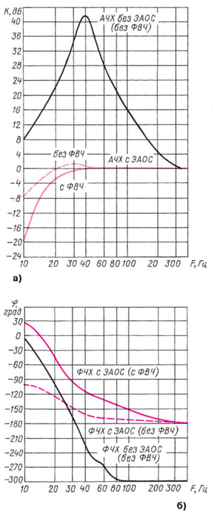
Consider the path of the main signal from the source, which begins with a second-order high-pass filter implemented according to the Sallen-Kay scheme on DA1.1 and C1, C2, R1, R2. Selecting the cutoff frequency fc = 21,4 Hz was made after analyzing the results of measuring the frequency response for sound pressure with the introduced EAOS. From the output of the HPF, the signal is fed to the resistor R3, which is one of the elements of the adder, and then through the capacitor C3 to the input of the PUNCH. This capacitor provides DC isolation of the non-inverting amplifier on DA2.1 from the HPF and elements in the EAOS circuit. The choice of nominal values of the R5С3 circuit elements is made on the basis of their minimal influence on the frequency response and phase response at f<10 Hz. PUNCH is implemented on the DA2.1 and DA2.2 op-amps, and the amplifier on DA2.1 provides the necessary depth of the EAOS, and the second-order HPF with fc = 290 Hz, included in the OOS circuit for DA2.1, sets the upper frequency of the EEA band. The measured frequency response and phase response for the PLF are shown in Fig. . 6.
Selection of the resistance ratio of resistors R7/R6 and cutoff frequency fc = 290 Hz for HPF on DA2.2 is made taking into account the provision of maximum gain at a frequency of f = 40 Hz. Limitations in the steepness of the HPF are caused by stability issues. From the PUNCH output (point A), the signal is fed to the PA input to the DA3.1 op amp and then to the equivalent of Gr on DA3.2 (see Fig. 1) with an output (point B) to the EAOS depth controller (R14). The EAOS signal path starts from the symmetrical input of the control panel (points C and D), implemented on the op-amp DA5.1 with a voltage gain of Kу = 1. The subsequent (main) amplification occurs on a non-inverting amplifier assembled on the op-amp DA5.2 with Kу=1+R22/R20. Capacitor C16 eliminates the penetration of signals with a constant component from previous stages to the input DA5.2, and its capacitance is chosen taking into account the small effect on the frequency response and phase response in the region of the lower frequency of the EAOS. Elements C17 and R21 serve to correct the frequency response and phase response at the upper frequency of the EAOS band at its great depth. The Linkwitz corrector (CL) following the PU produces the necessary correction of the frequency response and phase response, which are presented in the graphs of Fig. 7. The calculation of the CL elements was made on the basis of the analysis of the frequency response (Fig. 8, a) and the phase response (Fig. 8, b) of the system before the introduction of the EAOS, and also taking into account the provision of a small frequency response non-uniformity, with a maximum failure of the frequency response at a frequency fн = 30 Hz by no more than 0,9 dB. The final link in the EAOS signal chain is a second-order high-pass filter implemented according to the Sallen-Kay scheme on DA1.2 and C22, C23, R29, R30 with a choice of cutoff frequency fc2 = 1,05 fc1= 1,05 290 = 305 Hz, where fc1 - HPF cutoff frequency in PUNCH on DA2.2, equal to 290 Hz.
The results of measurements of the frequency response and phase response of the EAOS signal path from the input (point C) to the output (point E) are shown in the graphs of Fig. 9. The output signal of the EAOS (at point E) is mixed through the resistor R4 with the main signal at the input of the PUNCH. The selected resistor resistance ratio R4/R3 ≈ 2 provides both sufficient noise immunity and sufficient margin for the required maximum voltage from the DA1.2 output, taking into account the sensitivity of the system (Uvh = 2,3 V) and a large depth of EAOS.
Requirements for the EAOS sensor (microphone) 1. The maximum allowable, measured sound pressure level, limited by the THD value of not more than 0,2% in the frequency band 1 ... 300 Hz, not less than 40 dB more than the sound pressure level specified at a distance of 1 m. 2. Uneven frequency response in the frequency band 1 ... 300 Hz - no more than ± 0,2 dB. 3. Directional pattern - circular. 4. Stability of parameters for a long time of operation with changes in temperature, humidity and pressure of the environment in real operating conditions. A ready-made measuring microphone that meets the above requirements, or a self-made microphone can be used as a sensor. In the latter case, you only need to purchase a capsule from a classic condenser (for example, MK-265 or AKG CK62-ULS) or electret microphone. The capsule must be supplemented with a microphone amplifier (MU), which, usually in order to reduce the penetration of various interferences, is placed in the same housing with the capsule. Taking into account the close location of the microphone in relation to the surface of the EDG diffuser, and hence the receipt of a sufficiently large signal from the MU output, it is possible to significantly simplify the MU circuit by using a voltage follower. Two possible schemes of such MUs are shown in Figs. 10, where separate transistors or integrated circuits are used. A feature of these MUs is a high input impedance to achieve a low cut-off frequency of the SV band when working together with a signal source in the form of a microphone, which in our case is a capacitive sensor with a low capacitance. This capacitance, together with the resistor R1, determines the lower frequency of the measurement band f ≈ 0,5 ... 1 Hz with a decrease in the frequency response of no more than 0,2 dB. In MU in Fig. 10a, a deep common OOS for direct and alternating current is used by connecting the collector of the transistor VT2 to the source VT1, which ensures the stabilization of the modes. In addition, the MU also has a POS for voltage from output 1 through the resistor R1, which increases the input resistance of the MU to Rvh = R1/(1 - Kу), where Kу - voltage transfer coefficient from the input (gate VT1) to output 1. The voltage drop across R3 sets the bias voltage (Uy) for VT1, providing zero potential at output 1.
The resistance of the resistor R4 is selected according to the maximum attenuation of external interference (common mode) acting on the signal transmission line to the symmetrical input of the device for further signal amplification (input of the control panel in the diagram in Fig. 5). The minimum interference will correspond to the equality of the AC resistances for outputs 1 and 2 (relative to the common wire). Such a connection of the output of the MU with the subsequent device is called quasi-symmetrical. The stabilizer on DA1 serves to reduce the requirements for the amplitude of ripples from the power supply -U. In the MU scheme in Fig. 10, and transistor VT1 can be replaced by another one with similar parameters (cutoff voltage and drain current at Uy = 0). Transistor VT2 can also be replaced by any other corresponding structure with low noise level at h21э ≥ 200. In the MU scheme according to fig. 10, b, the output resistance at output 1 is close enough to zero, therefore, with a quasi-symmetrical connection with a further amplifying device, a common ("zero") wire can be used. In this version, it is also possible to use other types of microcircuits that meet the requirements for noise and input resistance Rvh 10 ≥10 Ohm. As can be seen from the MU diagrams in Fig. 10, one of the capsule leads is connected to the negative circuit of the power source. In this case, the best result in reducing the penetration of interference is achieved when the capsule body is connected to a power source, the polarity of which can be changed to positive with a corresponding change in the type of stabilizer and its connection. Literature
Author: A. Syritso
Artificial leather for touch emulation
15.04.2024 Petgugu Global cat litter
15.04.2024 The attractiveness of caring men
14.04.2024
▪ Panasonic Toughbook 55 rugged laptop ▪ Total Surveillance in New York ▪ Autonomous powered marine robot drone ▪ Nvidia AI systems for construction sites
▪ section of the site Standard instructions for labor protection (TOI). Selection of articles ▪ article Of course, I promised, but there is a limit to everything. Popular expression ▪ article What color noises, besides white noise, exist? Detailed answer ▪ article Adjuster of CNC machines. Job description ▪ article Imported radioelements. Encyclopedia of radio electronics and electrical engineering ▪ Article Catch a finger. Focus secret
Home page | Library | Articles | Website map | Site Reviews
www.diagram.com.ua |


 Leave your comment on this article: