|
|


 Arabic
 Bengali
 Chinese
 English
 French
 German
 Hebrew
 Hindi
Hindi Italian
 Japanese
 Korean
 Malay
Malay Polish
 Portuguese
 Spanish
 Turkish
 Ukrainian
 Vietnamese
|
ENCYCLOPEDIA OF RADIO ELECTRONICS AND ELECTRICAL ENGINEERING Homemade isodynamic emitters based on 10GI-1 heads. Encyclopedia of radio electronics and electrical engineering
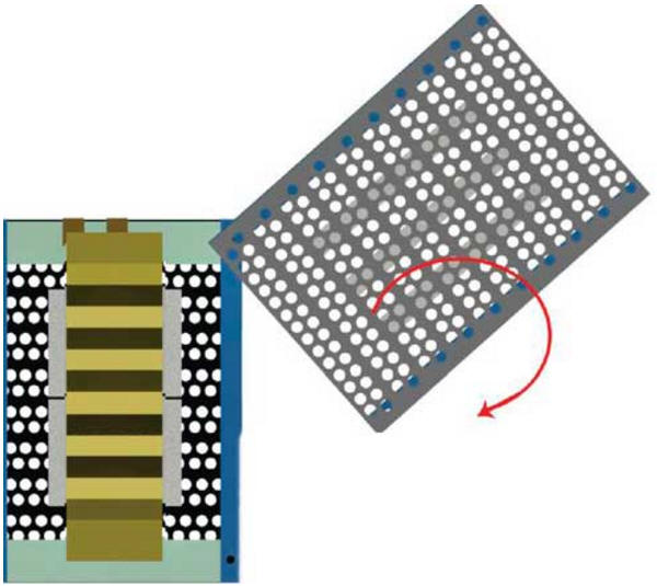
Encyclopedia of radio electronics and electrical engineering / Speakers Radio amateurs are offered a description of the design of an isodynamic radiator for reproducing musical signals in the medium and high frequencies. Together with these emitters, the author installed a group of dynamic drivers with light diffusers in a self-made speaker, using them in the bass band. For the highest frequencies, the author also preferred to use self-made ribbon radiators, the design of which was presented to him earlier in Radio, 2012, No. 12. Probably, many radio amateurs are familiar with domestic isodynamic heads 10GI-1, designed for high-quality reproduction of the high-frequency components of an audio signal. In the design of isodynamic emitters, a flat coil-membrane transmits electromechanical vibrations to the air medium "without an intermediary" in the form of a pattern, reproducing more accurately the fronts of sound signals, which contain an important part of musical information (timbre). It is believed that any non-traditional sound emitter is difficult to make, but the magazine "Radio" has already given examples of the "home" production of electrostatic [1, 2] and tape [3] sound emitters. Isodynamic heads can also be assembled independently [4]. The manufacture of the isodynamic heads described below was aimed not only at repeating a good previously produced design, but also, if possible, shifting the lower limit of the operating frequency band in order to capture the mid-frequency band as well. To lower the boundary, it was necessary to expand the gap between the magnets in order to increase the free movement of the membrane. The use of stronger neodymium magnets instead of ferrite ones compensated for the consequences of a decrease in magnetic flux. To repeat the design described below, 12 bar magnets with dimensions of 50x10x5 mm (in each emitter) will be required. Membrane with flat coils can be ordered at the St. Petersburg Diffuzor LLC (repair kit 10GI-1-16 with a coil resistance of 16 Ohm!) Or you can make it yourself using the technologies described in the relevant branches of specialized Internet resources (forums). On fig. 1 shows the structure under consideration in expanded form.
On fig. 2 shows a top view of the structure. Here, three rows of bar magnets with the specified polarity are glued onto two perforated steel sheets 2 mm thick.
On two edges of each sheet (Fig. 3) steel bars of square section 10x10 mm are fixed. Holes are drilled in them and in perforated sheets, through which four pins pass, fastening both halves of the magnetic system during final assembly.
In the photo of fig. 4 shows the preparation (cutting) of the membrane with a flat coil. The outer part of the base at the point where the printed pattern of the coil ends is removed.
Then, with the help of gears fixed on the shafts (for example, from old printers), the membrane is corrugated (Fig. 5). The resulting shape allows you to easily fix the membrane between the magnetic systems, without limiting its free movement.
Before gluing the membrane on one of the halves of the magnetic system, it is necessary to position it, as shown in the photo fig. 6, three damping pads made of thin fiber (clothing insulation material).
The side spacers should slightly touch the edges of the membrane, but not cover the entire radiation surface. The middle damping strip should fall on the wide central conductive track. After gluing the film and soldering the current-carrying conductors to the copper petals-leads (photo in Fig. 7), the front half of the required structure is formed.
Then another layer of thin fiber is carefully laid on top, covering the entire back of the surface (photo in Fig. 8). In this way, "centering" and the actual air gaps between the magnetic system and the membrane with the coil are formed.
The use of damping pads eliminates membrane resonances and allows you to get a clear sound at frequencies above 450 Hz. Next, the studs are threaded into the frame, and the second part of the magnetic system is put on them. In order not to damage the delicate membrane by accidental chaotic adhesion of parts, the upper half of the structure is first fixed with only one pin at maximum
The stud is baited with a nut for a couple of turns, then both halves of the magnetic system are turned until the rest of the mounting holes are aligned, controlling the passage of the "sticking" zones of the magnets. A baited hairpin will not allow halves to go into uncontrolled "sticking" when turning. With correctly "phased" magnets, the assembled halves of the structure should show a mutually repulsive force. Fixation is carried out on the remaining studs, then the structure is evenly tightened (photo in Fig. 10). In the position of the magnetic system fixed during assembly, oppositely located magnets create magnetic field lines directed along the plane of the coil and the membrane.
The finished structure shown in the photo in fig. 11, made in duplicate and is currently used as part of a three-way speaker (photo in Fig. 12) as midrange emitters with an operating frequency band of 800 Hz ... 10 kHz. The heads are connected through first-order filters, which provide minimal transient and phase distortion.
As high-frequency emitters, self-made tape dynamic heads are used, the principle of operation of which is described in [2], but of a simpler design. The need to use additional high-frequency emitters is due to the decrease in the sound pressure of the isodynamic emitter at frequencies above 10 kHz. The reason for the insufficient sound pressure in this area is probably due to the small aperture area of the holes in front of the front part of the radiator, since in the original 10GI-1 head the front part in front of the membrane is made in the form of open rectangular ports. The low-frequency group emitter in each of the stereo speaker channels is made of seven dynamic heads installed in an open case. Dynamic heads 5GDSh-4 and 4GD-28 (with a voice coil resistance of 4 ohms) are electrically connected in series, as shown in the crossover circuit in Fig. 13. This inclusion allows you to get the lower limit of reproducible frequencies from 52 Hz.
The use of several dynamic heads with a light movable system in the form of group radiators makes it possible to obtain a fast response for low-frequency signals as well. Thus, according to the author, it was possible to combine classical dynamic heads with isodynamic and tape radiators. The small stroke of the diffusers, due to the greatly increased total area and the low power supplied to an individual head, also implies small non-linear distortions at low frequencies. When operating such a speaker, the power achieved by common UMZCH (50 ... 60 W at a load with a resistance of 4 Ohms) will actually not exceed 10 ... 15 W. Note. Corrugation of the entire surface of the membrane, apparently, is not necessary. Membrane displacements during the reproduction of sound signals in the MF band are not so large in comparison with the gaps between the magnets formed in the structure. Therefore, it can be assumed that the corrugation along the two edges of the membrane (outside the bar magnets) will provide sufficient flexibility and compliance of the moving system. The damping fiber layer in this case can be placed (pasted) only in the corrugated part of the membrane. Literature
Author: S. Moshev
Artificial leather for touch emulation
15.04.2024 Petgugu Global cat litter
15.04.2024 The attractiveness of caring men
14.04.2024
▪ A new kind of space balloon for space travel ▪ Transient voltage suppressors from ON SEMICONDUCTOR ▪ Innovative orbital housing concept from Airbus ▪ First 200V DirectFET Transistor
▪ site section Field strength detectors. Article selection ▪ article totalitarian state. Popular expression ▪ article What part of the body is almost the same in size in all adults? Detailed answer ▪ article Work on waxing machines. Standard instruction on labor protection
Home page | Library | Articles | Website map | Site Reviews
www.diagram.com.ua |


 Leave your comment on this article: