|
|


 Arabic
 Bengali
 Chinese
 English
 French
 German
 Hebrew
 Hindi
Hindi Italian
 Japanese
 Korean
 Malay
Malay Polish
 Portuguese
 Spanish
 Turkish
 Ukrainian
 Vietnamese
|
ENCYCLOPEDIA OF RADIO ELECTRONICS AND ELECTRICAL ENGINEERING Improvement of the active indoor KB antenna Encyclopedia of radio electronics and electrical engineering / HF antennas The receiving antenna, described by the author in the article "Active KB range indoor antenna" ("Radio", 2009, No. 7, pp. 16-18), has good characteristics, but is not protected from the so-called common-mode interference (they penetrate the input of the RF amplifier and together with the useful signal enter the input of the receiver). To combat them, differential amplifiers are used. By replacing the single-field transistor amplifier used in the above design with such an amplifier, it is possible to significantly reduce its sensitivity to common-mode interference and thereby improve the reception quality.
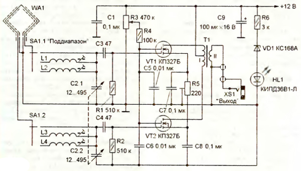
The scheme of the proposed version of the active antenna is shown in fig. 1. The differential amplifier is assembled on double-gate field-effect transistors VT1 and VT2, the load of which is the matching RF transformer T1. From its secondary winding, the signal enters the XS1 socket, and from it, via a shielded cable, to the socket of the external antenna of the radio receiver. Magnetic antenna WA1 - shielded single-turn frame. Its design is similar to that described in the article mentioned above, but it is connected differently: one output of the frame through the contacts of the SA1.1 switch section is connected to the input of the upper (according to the circuit) arm of the amplifier, the other (through the contacts of the SA1.2 section) - to the input of the lower. To improve the symmetry, the "extension" coils L1, L2 and L3, L4, which serve for coarse tuning of the antenna in frequency, are included at both inputs of the amplifier, and smooth tuning is carried out by a double block of capacitors of variable capacitance C2, the sections of which, in contrast to the above design, used separately. Signals with the frequency to which the antenna is tuned arrive at the inputs of the amplifier in antiphase, therefore, in the RF transformer T1, they are added in phase and their amplitude increases. Signals with frequencies that differ from the tuning frequency, as well as induced interference signals from surrounding household equipment, enter the amplifier inputs in phase, so they are added in antiphase in the transformer and their amplitude decreases. The gain of the cascade is regulated by changing the voltage at the second gates of the transistors coming from the engine of the variable resistor R3. The differential amplifier uses resistors and capacitors of the same types as the single transistor amplifier. RF transformer T1 is wound with PEV-2 0,1 wire on an annular magnetic circuit with a diameter of 8 ... 10 mm made of ferrite with a magnetic permeability of 600 ... 1000. Winding I contains 30 turns with a tap from the middle, winding 11-10 turns. For better symmetry, the primary winding should be wound with a wire folded in half (15 turns), and then connect the end of one wire to the beginning of the other and thus obtain a tap. Coils L1, L3 (16 turns each) and L2. L4 (50 turns each) is wound with PEV-2 0,2 wire directly on threaded trimmers with a diameter of 4 and a length of 11,5 mm made of carbonyl iron (used in armored magnetic cores SB-12a). It is desirable to select field-effect transistors for the same drain current at several values of the gate voltage.
Amplifier parts are mounted on the side of the printed conductors of the board made of double-sided foil fiberglass with a thickness of 1 ... 1,5 mm. made in accordance with Fig. 2. Opposite side foil is used as common wire. For the passage of the leads to be connected to the parts, 14 holes are drilled in the board. The dimensions of the board are the same as those of the amplifier on a single transistor, which allows replacement without significant modification of the design of the active antenna. Setting up a differential RF amplifier comes down to setting the same current through the transistors. To do this, the primary winding of the transformer T1 is temporarily replaced with the same constant resistors with a resistance of 200 ... 300 Ohms, the slider of the resistor R3 is set to the middle position and, by connecting a DC voltmeter to the drains of the transistors, zero voltage is set with the tuning resistor R5. If necessary, the boundaries of the subranges are shifted by the same change in numbers turns of inductors L1, L3 and L2, L4 (if the boundary needs to be shifted towards higher frequencies, the number of turns is reduced, and if, on the contrary, towards lower frequencies, they are increased). Author: I. Nechaev, Moscow; Publication: radioradar.net
Machine for thinning flowers in gardens
02.05.2024 Advanced Infrared Microscope
02.05.2024 Air trap for insects
01.05.2024
▪ A new way to cool semiconductors ▪ NASA will send astronauts to Venus ▪ Hydrogen crossover Audi H-Tron Quattro ▪ WiMAX Infrastructure Development Platform ▪ Panel thermostats series 7T81 from Finder
▪ section of the Antenna website. Article selection ▪ article Tsar-Hunger. Popular expression ▪ article How tall are pygmies? Detailed answer ▪ Mount Kilimanjaro article. Nature miracle ▪ article The first radio receiver. Encyclopedia of radio electronics and electrical engineering
Home page | Library | Articles | Website map | Site Reviews
www.diagram.com.ua |

 Leave your comment on this article: