
|
|
ENCYCLOPEDIA OF RADIO ELECTRONICS AND ELECTRICAL ENGINEERING The first radio receiver. Encyclopedia of radio electronics and electrical engineering
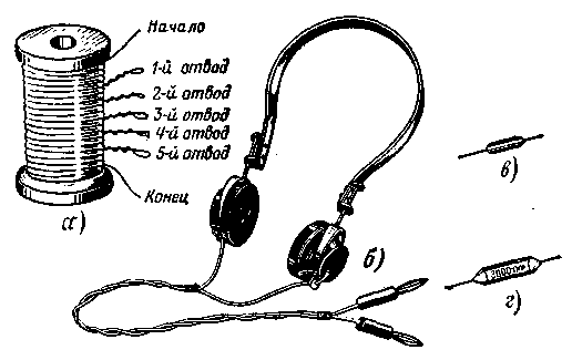
Encyclopedia of radio electronics and electrical engineering / Beginner radio amateur The detector receiver can be assembled in a box or mounted on a plank called a panel. Such a receiver, if you want, you can make later. Now I propose to start assembling an experimental detector radio receiver. You will need all the same, and it will work in the same way, but it will fly on the table in expanded form. The main advantage of such an experienced radio receiver is that it is easy to make any changes and additions to it, to correct errors by simply reconnecting the conductors. Experiments with it will help you understand the principle of operation of several variants of detector receivers, get the first practical design skills. For such a receiver, and in the future for other receivers, you need: a coil (Fig. 26, a), electromagnetic headphones, for example, TON-1 type (Fig. 26, b), a detector (Fig. 26, c), the role of which can perform a point diode, for example, type D9 or D2 with any letter, index, several capacitors of constant capacitance (Fig. 26, d), clips or pads with plug sockets and some other details.
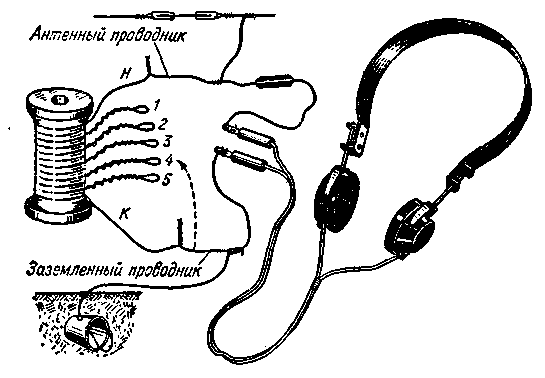
For the coil, a winding wire of the PEL brand (Wire with Enamel Lacquer-Resistant Insulation) or PEV (Wire with Enamel High-Strength Insulation) with a thickness of 0,2-0,3 mm is required. Winding wires of these brands and their thickness (without insulation) are designated as follows: PEL 0,2, PEV 0,3. Of course, wires of other brands are also suitable, for example, PBD - with insulation from two (letter D) layers of cotton yarn (letter B), or PELSHO - with enamel varnish-resistant insulation and one (letter O) layer of natural silk (letter Sh). It is only important that the insulation is intact, otherwise there may be a short circuit between the turns of the coil. On the spool of thread, using it as a frame, wind in bulk 400-450 turns of the recommended wire, making taps every 75-80 turns and twisting the wire in these places with loops. Let's say that you wound 450 turns and made taps every 75 turns. The result was a multilayer coil with five taps (as in Fig. 26, a). The sections between the taps, as well as between the beginning of the coil and the first tap, and between the last tap and the end are called coil sections. It happens that during the winding of the coil the wire breaks or one coil is not enough for the whole coil. In this case, the ends of the wire to be spliced must be stripped of insulation and tightly twisted. It is desirable to solder the twist and be sure to wrap it with insulating tape. If, however, it falls near a branch, then it is better not to spare a few turns of wire and make this connection in a loop. And now, young friend, strip the ends of the leads and taps of the coil from the insulation, only being careful not to break the wire, and proceed to assemble your first radio. Connect the beginning of the coil n (Fig. 27) to one of the outputs of the detector, and the end of the coil to one of the contact legs of the telephone cord. The remaining free outputs of the detector and telephones
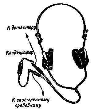
connect with a piece of wire. To the conductor going from the beginning of the coil to the detector, firmly screw the antenna wire, after stripping the end of it from insulation. This conductor of the receiver will be called antenna. Screw the ground wire to the conductor connecting the end of the coil to the phone. We will call it a grounded conductor. During the experiments, it will have to be switched from one coil output to another (shown in dashed line in Fig. 27), without changing the ground connections to the telephones. Let's take a "walk" through the chains of the resulting receiver. From the beginning of the coil and along the antenna conductor, we get to the detector, and from it to the headphones. Through the phones, then along the grounded conductor, through all the turns of the coil, we come to the starting point n. The result was a closed electrical circuit, consisting of a coil, a detector and telephones. This circuit is called the detector circuit. If there is a break somewhere in it, poor contact between the parts, for example, a loose twist, the circuit will be broken and the receiver will not work. The shortest path from the antenna to the ground is through the coil. A high-frequency current will go along this path, excited in the antenna by radio waves. This current will create a high frequency voltage at the ends of the coil, which will induce a current of the same frequency in the detector circuit. A circuit consisting of an antenna, coil and ground is called an antenna circuit or antenna circuit. Pay attention: the coil of your receiver is included in both the detector and antenna circuits. Having become acquainted with the receiver circuits, put the phones on your head, press them closer to your ears, listen. It is possible that you will not hear anything right away even with a known good antenna and grounding, a pre-tested detector and telephones. This is because the receiver is probably not tuned to a broadcast station that can be heard well in your area, or you are in a transmission break. You can tune such a receiver by changing the number of turns of the coil included in the antenna circuit. On fig. 27 all 450 turns of the coil are included in the antenna circuit. But if the grounded conductor is disconnected from the end of the coil and connected, for example, to tap 5, then not 450, but 375 turns will be included in the circuit. If this conductor is switched to tap 4, 300 turns will be included in the circuit. When switching it to tap 3, 225 turns will be included in the antenna circuit, etc. In this case, the lower sections will not be included in the circuit and will not participate in the operation of the receiver. Thus, by switching a grounded conductor, you can include in the circuit 75, 150, 225, etc. up to 450 turns through 75 turns. Remember: the longer the wavelength of the broadcasting station to which the receiver can be tuned, the greater the number of turns of the coil must be included in the antenna circuit. Your receiver can be tuned to both mediumwave and longwave broadcasting stations. But, of course, you can't receive transmissions from every station. Remote stations will not be heard on the detector receiver. Now start setting up the receiver by connecting the grounded conductor first to pin 5, then to pin 4, and so on to pin 1. At the same time, make sure that the coil taps and the connecting conductors do not touch, and the twists are strong. Otherwise, the receiver will not work at all, or crackles and rustles will be heard in the phones that interfere with reception. Electrical contacts will be more reliable if the joints of conductors and parts are soldered. Having tuned the receiver to one station, remember the number of turns included in the circuit at which the station is heard with the greatest volume. Then try to "find" another station in the same way. Hope you have some success. Try to improve the performance of the receiver. Without changing the settings of the receiver, connect a capacitor in parallel with the telephones (Fig. 28), called in this case a blocking capacitor. Its capacitance can be in the range from 1000 to 3000 pF (picofarad). At the same time, the volume of the sound of the phones should increase slightly. If broadcasting stations are more than 150-200 km from where you live, turn on the blocking capacitor at the very beginning of the experiment.
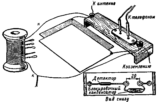
Tuning the receiver by only jumping the number of turns of the coil is very simple. But it does not always allow to achieve precise tuning of the circuit to the frequency of the station. Fine tuning can be done in several other ways. For example, with a nail. Try! Tune the receiver in a familiar way to the radio station wave and insert a thick nail or a bolt of a suitable diameter into the hole in the coil frame. What happened? The reception volume slightly increased or, conversely, decreased. Pull the nail out of the coil - the volume will be the same. Now slowly insert the nail into the coil and just as slowly remove it from the coil - the volume of the receiver will change slightly, but smoothly. Empirically, you can find such a position of a metal object in the coil, in which the sound volume will be the best. This experience allows us to conclude that a metal object placed in the coil affects the tuning of the circuit. With this method of tuning the receiver, only, of course, using a ferromagnetic core better than a nail, you will get acquainted in this conversation and will often use it in the future. Now introduce a variable capacitor into the receiver and use it to tune the antenna circuit to the radio station. For the convenience of this and several subsequent experiments with a detector receiver, on a plywood board measuring approximately 25 x 70 mm, mount a block with sockets, two clamps, a detector and a blocking capacitor, connecting them under the board, as shown in Fig. 29.
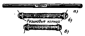
Install the block with sockets on the plank as follows: drill two holes in it with a diameter of 6-8 mm with a distance of 20 mm between the centers and insert the "tails" of the plug sockets into them. Strengthen the block on the plank with screws or screws with nuts. Connect the beginning of the coil and the antenna to the terminal to which the detector is connected, and connect the end of the coil and ground to the second terminal connected to the telephone jack. The role of a variable capacitor will be performed by two metal plates with dimensions of approximately 150x150 mm; use for this purpose, for example, the tin of large cans. Solder conductors 250-300 mm long to the plates. Using these conductors, connect one plate to the antenna clamp, and the other to the ground clamp. Put the plates on the table one next to the other, but so. so that they do not touch, and tune the receiver to the radio station only by switching coil sections with a grounded conductor. Now bring the ground plate to the plate connected to the antenna. If the volume increases, bring the plates closer together and finally put one plate on top of the other, laying a sheet of dry paper between them (so that there is no electrical contact). Find such a mutual arrangement of the plates, in which there will be fine tuning. If, when the plates approach each other, the reception volume decreases, switch the grounded conductor to the outlet closest to the beginning of the coil and again bring the plates closer, achieving the highest volume. In this experiment, coarse tuning of the receiver was carried out by changing the inductance of the coil by switching sections, and fine tuning was carried out by changing the capacitance of the plate capacitor. Remember: the inductance of the coil and the capacitance of the capacitor when tuning the receiver to the radio station are interconnected. One and the same radio station can be listened to by including a larger number of turns in the antenna circuit of the receiver, i.e., a larger coil inductance, but with a smaller capacitor capacitance, or, conversely, with a smaller coil inductance, but a larger capacitor capacitance. The next experiment is tuning the antenna circuit of the detector receiver with a high-frequency core. In addition to the detector, phones and capacitors, the experiment will require: a 600NN or 400NN ferrite rod with a diameter of 7-8 mm and a length of 140-160 mm (such rods are used for magnetic antennas of transistor receivers) and two coils, one of which is designed to receive long-wave radio stations , the second - to receive radio stations in the medium wave range. The appearance of the ferrite rod and the design of the coils are shown in fig. 30. The inner diameter of the coil frames should be such that the rod enters them with little friction. The length of the long-wave coil frame should be 100-110 mm, and the medium-wave coil 80-90 mm.
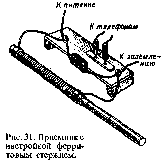
Glue the frames from writing paper in 3-4 layers on the rod, using it as a blank. Do it like this. First, roll the rod into a strip of paper one turn. Then smear the inside of the remaining part of the paper with a thin and even layer of BF-2 glue, roll the rod tightly into it and, without removing the frame from the rod, dry it well. First, wrap the rod with one or two layers of thin paper so that the frame does not stick to it. When the frame dries, remove it from the rod, remove the paper layer and dry it in a warm place. Finished frames must be rigid. Now, on a frame designed for a long-wave coil, wind 300-320 turns of PEV or PEL 0,2-0,3 wire, laying the wire in a tight row, turn to turn. The coil of the medium wave range should contain 75-80 turns of the same wire, but laid on the frame in a discharge (with a small distance between the turns) so that the total length of the winding is 60-70 mm. Before winding the coil, insert the rod into the frame. Do not pull the wire too hard, otherwise the frame will shrink and it will be difficult to pull the rod out of it. To prevent the extreme turns of the coils from falling off, fix them on the frame with rings cut from a rubber or PVC tube, or with threads. Get started with experience. Connect the medium wave coil to the previously made prefix as shown in fig. 31. Between the antenna and ground terminals, i.e., parallel to the coil, turn on a mica or ceramic capacitor with a capacity of 120-150 pF. Press the phones closer to your ears, concentrate and slowly insert the ferrite rod into the coil. Gradually deepening the rod into the coil, you should hear the transmissions of those broadcasting stations in the medium wave range, which can be received in your area on a detector receiver. The longer the radio wave, the deeper the rod must be inserted into the coil. Empirically find such a position of the rod in the coil, in which the station signals are heard, and make a mark on the rod with a pencil. Using it as a division of the scale, you can quickly tune the receiver to the frequency of this station.
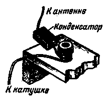
After that, connect another capacitor in parallel with the coil with a capacity of 390-470 pF. How did this affect the tuning of the receiver? The volume remains the same, but to tune to the same station, the rod has to be inserted into the coil less. Completely remove the capacitor, leaving only the coil on. What happened? To tune the receiver to the same station, the rod must be inserted more into the coil. Repeat exactly the same experiments with the long-wavelength coil. Memorize the results, but rather write them down. It is possible that with this coil the longest station in the medium wave range will be heard even when the rod is not inserted into the coil at all. But it will be more difficult to achieve fine tuning to the wave of this station than with the first coil. So you will get acquainted with another version of the detector receiver - a dual-band one tuned with a ferrite core - and at the same time find out which stations can be received on it. What conclusions can be drawn from experiments with this receiver? Main two. Firstly, a ferrite rod has a much stronger effect on contour tuning than a metal object. Secondly, with the help of a ferrite rod, you can smoothly and accurately tune the receiver circuit to the desired radio station. I recommended winding the turns of the medium-wave coil in a discharge. Why? Only in order to more accurately tune the receiver circuit to the radio station wave. It can be wound and turn to turn. It would occupy a section 15-20 mm wide on the frame. But in this case it would be more difficult to tune the receiver, since the slightest displacement of the rod would greatly change the inductance of the coil. By winding the coil in a discharge, you thereby, as it were, stretched the range of waves overlapped by the contour of the successor. Try to move the turns of the coil, and you will see that it is more difficult to tune the receiver with such a coil. The discharge could also be laid with turns of the coil of the long-wave range. But this is not necessary, since its winding is already wide enough. A few more experiments with this receiver. Tune it to any radio station, and then, without changing the settings, connect a 47-62 pF capacitor between the antenna and the antenna clamp (Fig. 32). The volume of the receiver has decreased slightly. This happened because the capacitor changed the data, or as they say, the parameters of the circuit. Adjust the circuit with a ferrite rod, inserting it a little deeper into the coil. If, prior to the inclusion of an additional capacitor in the circuit, while receiving one station, another radio station close in frequency was listened to, now it will be listened to weaker, and possibly not interfere at all. The receiver began to more clearly distinguish the signals of the station to which it is tuned. Instead of a fixed capacitor between the antenna and the receiver, you can include a variable capacitor. With it, you can not only change the selectivity, i.e. selectivity, but possibly also tune the receiver.
And now do this: disconnect the antenna and ground from the receiver and turn on the detector between them, and connect telephones without a blocking capacitor in parallel with the detector. That's the whole receiver. Works? Quiet, perhaps? In addition, maybe two or three stations are heard at the same time? You should not expect better from such a receiver. Publication: N. Bolshakov, rf.atnn.ru
Traffic noise delays the growth of chicks
06.05.2024 Wireless speaker Samsung Music Frame HW-LS60D
06.05.2024 A New Way to Control and Manipulate Optical Signals
05.05.2024
▪ Device against decompression sickness ▪ World's first blood test for melanoma
▪ section of the Electrician website. PTE. Article selection ▪ article by Matsuo Basho. Famous aphorisms ▪ article Fainting. Health care ▪ article Radio game Find a mine. Encyclopedia of radio electronics and electrical engineering
Home page | Library | Articles | Website map | Site Reviews www.diagram.com.ua |


 Arabic
 Bengali
 Chinese
 English
 French
 German
 Hebrew
 Hindi
Hindi Italian
 Japanese
 Korean
 Malay
Malay Polish
 Portuguese
 Spanish
 Turkish
 Ukrainian
 Vietnamese
 Leave your comment on this article: