|
|


 Arabic
 Bengali
 Chinese
 English
 French
 German
 Hebrew
 Hindi
Hindi Italian
 Japanese
 Korean
 Malay
Malay Polish
 Portuguese
 Spanish
 Turkish
 Ukrainian
 Vietnamese
|
ENCYCLOPEDIA OF RADIO ELECTRONICS AND ELECTRICAL ENGINEERING Antenna Inverted V - Windom. Encyclopedia of radio electronics and electrical engineering
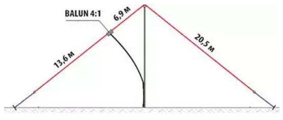
Encyclopedia of radio electronics and electrical engineering / HF antennas The Windom antenna, which has been used by radio amateurs for almost 90 years, got its name from the name of the American shortwave that proposed it. In those years, coaxial cables were very rare, and he figured out how to power a half-wavelength emitter with a single-wire feeder. It turned out that this can be done if the antenna feed point (connection of a single-wire feeder) is taken approximately at a distance of one third from the end of the radiator. The input impedance at this point will be close to the wave impedance of such a feeder, which in this case will operate in a mode close to that of a traveling wave. The idea turned out to be fruitful. At that time, the six amateur bands in use were multiple frequencies (non-multiple WARC bands only appeared in the 70s), and this point turned out to be suitable for them too. Not an ideal point, but quite acceptable for amateur practice. Over time, many variants of this antenna appeared, designed for different ranges, with the general name OCF (off-center fed - with power not in the center). In our country, it was first described in detail in the article by I. Zherebtsov "Transmitting antennas powered by a traveling wave", published in the journal "Radiofront" (1934, No. 9-10). After the war, when coaxial cables entered amateur radio practice, a convenient power option appeared for such a multi-band radiator. The fact is that the input impedance of such an antenna on the operating ranges is not very different from 300 ohms. This makes it possible to use common coaxial feeders with a wave impedance of 50 and 75 ohms for its power supply through high-frequency transformers with an impedance transformation ratio of 4:1 and 6:1. In other words, this antenna easily entered into everyday amateur radio practice in the post-war years. Moreover, it is still mass-produced for shortwaves (in various versions) in many countries of the world. It is convenient to hang this antenna between houses or two masts, which is not always acceptable due to the real circumstances of housing both in the city and outside the city. And, of course, over time, there was an option to install such an antenna using just one mast, which is more realistic to use in a residential building. This option is called Inverted V - Windom. The Japanese shortwave JA7KPT, apparently, was one of the first to use this option for installing an antenna with a radiator length of 41 m. This length of the radiator was supposed to provide it with operation on the 3,5 MHz band and higher HF bands. He used an 11 m high mast - for most radio amateurs this is the maximum size for installing a makeshift mast on a residential building. Radio amateur LZ2NW (lz2zk. bfra.bg/antennas/page1 20/index. html) repeated his version of Inverted V - Windom. Schematically, its antenna is shown in Fig. 1. The height of the mast was about the same (10,4 m), and the ends of the radiator were about 1,5 m away from the ground. To power the antenna, a coaxial feeder with a characteristic impedance of 50 ohms and a transformer (BALUN) with a coefficient transformations 4:1.
The authors of some variants of the Windom antenna note that it is more expedient to use a transformer with a transformation ratio of 50:6 with a feeder impedance of 1 ohms. But most antennas are still made by their authors with 4:1 transformers for two reasons. Firstly, in a multi-band antenna, the input impedance "walks" within certain limits near the value of 300 Ohm, therefore, on different ranges, the optimal values of the transformation ratios will always be slightly different. Secondly, a 6:1 transformer is more difficult to manufacture, and the benefit from its use is not obvious. The LZ2NW, using a 38 m feeder, obtained SWR values less than 2 (typical value 1,5) on almost all amateur bands. The JA7KPT has similar results, but for some reason it dropped out in SWR in the 21 MHz range, where it was greater than 3. Since the antennas were not installed in a "clear field", such a drop in a specific range may be due, for example, to the influence of the environment surrounding it " gland". LZ2NW used an easy-to-make BALUN, made on two ferrite rods with a diameter of 10 and a length of 90 mm from the antennas of a household radio. Each rod is wound in two wires with ten turns of wire with a diameter of 0,8 mm in PVC insulation (Fig. 2). And the resulting four windings are connected in accordance with Fig. 3. Of course, such a transformer is not intended for powerful radio stations - up to an output power of 100 W, no more.
Sometimes, if the specific situation on the roof allows it, the Inverted V - Windom antenna is made asymmetrical by attaching the BALUN to the top of the mast. The advantages of this option are clear - in bad weather, snow and ice, settling on the BALUN antenna hanging on the wire, can cut it off. Author: B. Stepanova
Machine for thinning flowers in gardens
02.05.2024 Advanced Infrared Microscope
02.05.2024 Air trap for insects
01.05.2024
▪ New Version of DC/DC Converter LT1936 ▪ Wind electricity on bacteria ▪ Nanotechnology for strengthening concrete
▪ section of the site Tips for radio amateurs. Selection of articles ▪ Montague and Capulet article. Popular expression ▪ article What is the largest fish in the world? Detailed answer ▪ article Autogyro-glider. Personal transport ▪ article Classification of intercoms. Encyclopedia of radio electronics and electrical engineering
Home page | Library | Articles | Website map | Site Reviews
www.diagram.com.ua |


 Leave your comment on this article: