|
|


 Arabic
 Bengali
 Chinese
 English
 French
 German
 Hebrew
 Hindi
Hindi Italian
 Japanese
 Korean
 Malay
Malay Polish
 Portuguese
 Spanish
 Turkish
 Ukrainian
 Vietnamese
|
ENCYCLOPEDIA OF RADIO ELECTRONICS AND ELECTRICAL ENGINEERING Electrically shortened loop antenna. Encyclopedia of radio electronics and electrical engineering
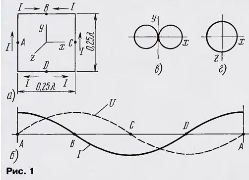
Encyclopedia of radio electronics and electrical engineering / VHF antennas In a number of practical cases, the dimensions of the antenna, commensurate with the wavelength, are unacceptably large. Therefore, electrically shortened (small) antennas were developed. It is also important that the antenna is the only element that emits or receives electromagnetic energy. One of the variants of such antennas, an electrically shortened loop antenna, is discussed in the article. The experiments were carried out at frequencies of 14, 27, and 430 MHz. A loop antenna has the best properties when it covers the largest area for a given perimeter, i.e., it is a round frame. But for the convenience of consideration, let us turn to the square frame and the vertical polarization of the emitted (received) waves (Fig. 1a).
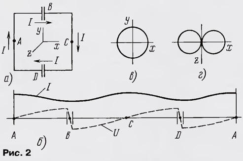
The directivity coefficient (DAC) of a square frame with a perimeter e = λ (λ is the wavelength) in free space compared to a half-wave dipole is 1,35 dB with a resistance of rΣ = 100 Ohm [1]. A vertically polarized square loop can be thought of as consisting of two half-wave vertical dipoles loaded at the ends (capacitive loading) and separated by a quarter wavelength. There is no up and down radiation, since the currents in the horizontal conductors of the frame cancel each other out. The distribution of current I and voltage U along the frame conductor is shown in fig. 1b. Points A and C, current antinodes, are points of zero potential. When the antenna is connected to the gap at point A, one dipole is supplied with current, and the other - at points B and D - with antiphase voltages. The radiation patterns of the frame located in free space, in the vertical and horizontal planes, are shown in fig. 1 c, d and are close in shape to the radiation pattern of a half-wave dipole [2]. The electrical shortening of the loop antenna can be carried out by increasing the capacitive load of the dipoles by turning on the voltage antinodes, i.e., at points B and D, capacitances, which additionally changes the phase of the voltage at these points by 180 ° (Fig. 2, a). Let's call this antenna a shortened loop antenna of two half-frames.
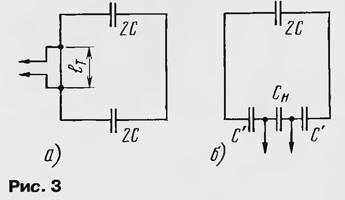
The current in the frame circuit now flows in only one direction (Fig. 2, b), i.e., the currents in the opposite conductors of the frame turn out to be oppositely directed relative to each other. This means that there is no radiation in the direction perpendicular to the plane of the frame, i.e., the radiation pattern is approximately a circle in the vertical plane and a "figure eight" in the horizontal (Fig. 2, c, d). If we consider two half-wave dipoles with oppositely directed equal currents as an analogue of this antenna, then the gain in the horizontal plane relative to the circular radiation pattern is 3,8 dB [1]. Thus, in its properties, this antenna approaches a magnetic antenna - an antenna with a constant current distribution along the loop contour, and radiating mainly the magnetic component of the electromagnetic field in the near zone. The antenna under consideration has four points of zero potential: A, C - antinodes of the current and B, D - midpoints of the distances between the plates of the capacitors - voltage nodes. Accordingly, the antenna can be powered near these points. The easiest way is to use a T-shaped matching when powered in the current antinode (Fig. 3, a) [2] or a capacitive voltage divider when connected to a voltage node (Fig. 3, b) [1].
Approximate parameters of the connecting circuit can be determined from the following considerations.
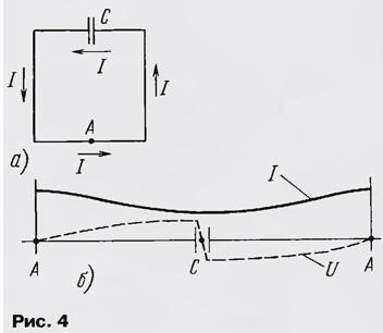
Another version of an electrically shortened loop antenna is known - a half-wave dipole with a capacitive load, folded into a frame (Fig. 4, a). To implement this antenna, the perimeter of the loop must be less than half the wavelength. Points of zero potential - point A and the middle of the distance between the plates of the capacitor C (Fig. 4, b). The radiation pattern approximately coincides with the radiation pattern of a loop antenna of two half-frames. The power line is connected near zero potential points, as is done in a loop antenna with two half-frames.
A shortened loop antenna of two half-frames is characterized by a more uniform distribution of the current amplitude along the loop conductor compared to a loop antenna with a continuous loop, therefore, with the same perimeters, it has a large radiation resistance rΣ and, as a result, a higher efficiency ηA (efficiency). The gain according to the measurement data reaches 3 dB at e/λ = 0,2. The study of a shortened loop antenna of two half-frames was carried out at frequencies of 14, 27 and 430 MHz. For a frequency of 14 MHz, a square frame made of copper wire with a diameter of 2 mm had a perimeter e = 0λ, capacitance 2C = 22 pF, quality factor of an unloaded frame Q = 100, radiation resistance rΣ = 2 Ω, input resistance in the current antinode rin = 10 Ω, efficiency ηA - 0,1 and bandwidth 0,3 MHz. To connect a cable with a wave impedance Pl = 50 Ohm, the capacitive voltage divider consisted of capacitors C = 47 pF and Cn = 510 pF, and the length of the frame conductor section for T-shaped matching eτ = 160 mm. Balancing was carried out using a ferrite ring and several turns of a coaxial cable [2]. The antenna was used as a room receiver for monitoring the work of amateur radio stations. In some cases, it was possible to reduce the level of interfering signals due to the symmetry of the antenna, which attenuates common-mode interference, and the presence of "nulls" in the radiation pattern. For a frequency of 27 MHz, several antennas were made from two half-frames with perimeters e = (0,1 ... 0,5)%. Their study gave the following. For the loop antenna under consideration, the radiation resistance drops very strongly with a decrease in size. It depends on the square of the area (or the fourth power of the perimeter of the circular frame). Therefore, for loop antennas with a perimeter e < 0,1 A, the radiation resistance is much less than the loss resistance, and the antenna bandwidth is determined only by the parameters of the antenna LC circuit. For a loop antenna with a perimeter e > 0.2A. the radiation resistance becomes commensurate with the loss resistance, the quality factor begins to fall, and the antenna bandwidth and efficiency increase. In addition, when feeding the antenna, it is desirable to strive to ensure that the central parts of the vibrators, i.e., the antinodes of the current, are free from connecting elements. Therefore, a capacitive voltage divider is preferable to a T-shaped matching. The 430 MHz loop antenna measured 36x22 mm and was made of silver-plated copper wire with a diameter of 1,5 mm. Capacitances 2C consisted of trimmer capacitors 1...5 pF. Asymmetric T-shaped matching was used. The cable braid with Pl = 50 Ω was connected to the zero potential point - current antinode, and the central core - at a distance of 10 mm from it. The bandwidth of the loaded antenna is 4,5 MHz, the efficiency is 0,05 ... 0,1. The considered loop antenna is symmetrical, does not require a counterweight, has zero potential points (which allows the use of conventional power supply methods), can be adjusted by variable capacitors, is not very sensitive to the presence of dielectric and weakly conductive objects in its immediate vicinity, and does not contain inductive matching elements. For a given perimeter, the shortest round loop antenna, consisting of two half-frames, powered through a capacitive voltage divider with the lowest possible losses in the frame material and capacitors, has the highest efficiency. Literature
Author: N. Turkin, St. Petersburg
A New Way to Control and Manipulate Optical Signals
05.05.2024 Primium Seneca keyboard
05.05.2024 The world's tallest astronomical observatory opened
04.05.2024
▪ The brain has a built-in noise reduction system ▪ Western Digital introduced the device 3 in 1 ▪ TV from SEIKO EPSON with a built-in photo printer ▪ Fast Charger for Smartphones
▪ site section Indicators, sensors, detectors. Article selection ▪ hang glider article. History of invention and production ▪ article Whose gravestone says he was the husband of another man's widow? Detailed answer ▪ article Pile cone. Legends, cultivation, methods of application ▪ article Marking of fluorescent lamps. Encyclopedia of radio electronics and electrical engineering ▪ article Two simple analog stabilizers. Encyclopedia of radio electronics and electrical engineering
Home page | Library | Articles | Website map | Site Reviews
www.diagram.com.ua |

 Leave your comment on this article: