|
|
ENCYCLOPEDIA OF RADIO ELECTRONICS AND ELECTRICAL ENGINEERING Antenna amplifier of the 1296 MHz band. Encyclopedia of radio electronics and electrical engineering
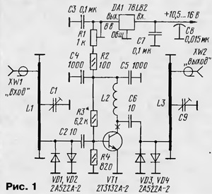
Encyclopedia of radio electronics and electrical engineering / VHF antennas To increase the range and quality of radio communications in the VHF bands, radio stations often use antenna amplifiers. Their main purpose is to increase the sensitivity of the entire radio receiving path and compensate for signal losses in feeders. On fig. 1 shows a diagram of a 1296 MHz antenna amplifier. It is assembled on a low-noise bipolar microwave transistor. Selective circuits L1C1 and L3C9 based on half-wave resonators are installed at the input and output of the amplifier. To protect the transistor from a powerful transmitter signal, limiting diodes VD1-VD4 are installed at the input and output of the cascade.
The DC transistor mode is set by a resistive voltage divider R3, R4 and load resistors R1, R2. The supply voltage recommended for this type of transistor is 7 V on the collector. With a tuned resistor R1, you can change the transistor current within 1 ... 10 mA. The power supply of the amplifier is stabilized by an integrated voltage regulator on the DA1 chip. The device uses parts of the following types: constant leadless capacitors K10-17v or similar imported ones, tuned capacitors - KPK-MT with a capacity of 2 ... 7 pF, a through capacitor - K10-51, B7. The tuned resistor is SPZ-19, the constants are P1-12, P1-4, MLT. The transistor indicated in the diagram can be replaced with KT3132A-2, KT3101A-2, 2T3101A-2, the stabilizer chip - with KR1157EN802A or B. The resonators L1, L3 are made of a strip of copper foil (preferably silver-plated) 0,2...0,4 mm thick, 5 mm wide and 58...60 mm long. The strip is bent in the form of a U-shaped bracket 48 ... 50 mm long and 4 ... 5 mm high, both ends of which are soldered to the common wire of the circuit board. Coil L2 is wound with wire PEV-2 0,2 on a mandrel with a diameter of 3 mm and contains 6 ... 7 turns. Most parts of the amplifier are placed on a printed circuit board made of double-sided foil fiberglass 1,5 mm thick. A sketch of the working side of the board and the location of the main elements on it are shown in fig. 2.
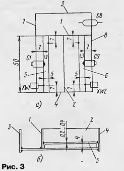
The foil on the second side of the board is used as a screen. Several holes are made in the board, through which the screen and the common wire of the working side are connected by soldering. The design of the amplifier is shown in fig. 3, and must be collected in a certain order.
First, all parts are mounted on the board, except for the feedthrough and trimmer capacitors, RF connectors, as well as resonators L1, L3. The board is the basis, on which the central partitions 1, 2 and side walls 3, 4 are then soldered. A cutout for the transistor is made in the partition 2. Resonators L1 (5), L3 (6) are soldered next. Lastly, side walls 7, 8 with RF sockets and capacitors C1, C9 are soldered to the board (also on both sides of the board). The capacitors, in turn, are soldered to the midpoints of the resonators L1 and L3, respectively. All required mounting dimensions are also shown in fig. 3. Setting up the amplifier comes down to tuning the input and output circuits to the center frequency of the range with tuning capacitors C1 and C9. The input impedance of the amplifier, and hence its SWR, can be changed by choosing the point of connection of the center conductor of the XW1 socket to the resonator L1. A tuned resistor R1 sets the required current through the transistor. This can be done by ear according to the best quality of receiving a weak signal, however, it should be noted that in this case the SWR of the amplifier will also change somewhat. The setting must be repeated several times. To increase the stability of the amplifier, a small-sized resistor (P1-4, P1-12) with a resistance of 5 ... 10Ω can be installed in the collector circuit of the transistor. The tuned amplifier is closed on top with a lid made of tinned sheet. To protect against moisture, tuned capacitors, as well as all joints from the outside, must be filled with an elastic sealant. The amplifier layout assembled by the author had the following parameters: gain -11 dB, bandwidth -3 dB - about 20 MHz, input SWR - no more than 1,2. Instead of a transistor, you can use a monolithic gallium arsenide chip MGA86563 (Nechaev I. "UHF antenna amplifier on a chip". - Radio, 1999, No. 4, pp. 8, 9), by turning it on, as shown in Fig. 4.
The gain of such an amplifier will be within 18 ... 20 dB, and the noise figure - no more than 1,6 ... 1,7 dB. Accordingly, you will have to adjust the topology of the printed circuit board. Author: I.Nechaev (UA3WIA)
A New Way to Control and Manipulate Optical Signals
05.05.2024 Primium Seneca keyboard
05.05.2024 The world's tallest astronomical observatory opened
04.05.2024
▪ Noise can raise blood cholesterol levels ▪ SEAGATE hard drives in TOSHIBA video recorders
▪ section of the site Microcontrollers. Article selection ▪ article Pythagoras. Famous aphorisms ▪ article Can animals count? Detailed answer ▪ Article Chastukha common. Legends, cultivation, methods of application ▪ article Belgian wheel ointment. Simple recipes and tips ▪ Article Magic wand. Focus Secret
Home page | Library | Articles | Website map | Site Reviews www.diagram.com.ua |


 Arabic
 Bengali
 Chinese
 English
 French
 German
 Hebrew
 Hindi
Hindi Italian
 Japanese
 Korean
 Malay
Malay Polish
 Portuguese
 Spanish
 Turkish
 Ukrainian
 Vietnamese


 Leave your comment on this article: