Combined antenna for 80 and 20 meters. Encyclopedia of radio electronics and electrical engineering

Encyclopedia of radio electronics and electrical engineering / HF antennas
 Comments on the article
This antenna (Fig. 1) does not differ in the original radio engineering solution, but the design itself is interesting in that it can be installed on the very edge of the roof of a residential building. It consists of two electrically independent antennas: a loop (DELTA LOOP) for a range of 20 meters and a shortened pin (GP) for a range of 80 meters.

The mast 1, about 3 m long, supporting the DELTA LOOP and part of the GP, is securely fixed to the railing 2 at the edge of the roof. In the upper part, to the mast, through insulating gaskets 4, an emitter of a range of 80 meters, 5,3 m long, is attached, made up of three segments of thin-walled duralumin pipes, which are inserted one into the other. A conductor 3 5 m long is attached to the lower part of the emitter 4,3, supported by a dielectric stretch 6. It goes to the matching block 7. In the lower part of the mast 1, just above the fence 2, a dielectric pipe 8 is attached. It consists of two rods 3.5 m long This tube supports the lower part of the frame 9. In the upper part, the frame is attached to the 80-meter range transducer through a dielectric insert (not shown in Fig. 1).
A matching transformer 11 is also located on the dielectric plate 13, which fixes the rods. Two extensions 12 additionally fix the mast. The antennas are fed through separate coaxial cables 10 and 14.
Schematically, the antennas are shown in fig. 2.

Frame 1, which has an input impedance of about 120 ohms, is fed through a balancing transformer 2 and a transforming quarter-wave line 3 with a wave impedance of 75 ohms. Power cable 4 is used with a characteristic impedance of 50 ohms.
The design of the upper frame insulator is shown in fig. 3.

A dielectric rod 1 is inserted into the upper section of the pipe of the emitter 80 of the range of 2 meters. Screw with nut 3 prevents the rod from falling into the pipe. In the upper part of the rod there is a through hole 4. through which the wire of the loop 5 passes.
The matching device for the range of 80 meters (Fig. 4) consists of an extension coil 8 and a choke 5. The coil is wound on a frame with a diameter of 6 cm and a length of 25 cm. It has 50 turns of bare copper wire with a diameter of 1,6 mm. Winding pitch - 1,6 mm. The braid of the supply cable 4 is connected to the end of the coil, and the point of their connection with conductor 6 to the "ground" is a metal fence. The central conductor of the cable is connected to the tap of 1 coil (approximately 1,5 turns, counting from the "cold" end of the coil).
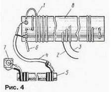
The emitter is also connected to the coil outlet (from about the 16th turn). On fig. 4 shows two taps - 2 and 3. The point is. that the operating frequency band of this emitter is relatively narrow (due to a noticeable shortening) and for operation at different ends of the range it is necessary to change the point of its connection to the matching coil. You can use a relay to switch.
Since the fence is not the best "ground", a choke 5 is introduced to eliminate currents through the braid of the supply coaxial cable. It is wound with two wires in isolation on the rod from the magnetic antenna of the broadcasting receiver. The number of turns of this inductor is about 20 (non-critical).
The number of turns of the extension coil was chosen by the author with a margin for experimentation, so you can try to tune it on a range of 160 meters.
Note that the GP length is close to a quarter wavelength for the 40m band. It requires only a small extension coil to operate, and the antenna should be relatively efficient, especially if additional counterweights are added on this band.
Author: JJ7XTV
 See other articles Section HF antennas.
Read and write useful comments on this article.
<< Back
 Latest news of science and technology, new electronics:
Machine for thinning flowers in gardens
02.05.2024
In modern agriculture, technological progress is developing aimed at increasing the efficiency of plant care processes. The innovative Florix flower thinning machine was presented in Italy, designed to optimize the harvesting stage. This tool is equipped with mobile arms, allowing it to be easily adapted to the needs of the garden. The operator can adjust the speed of the thin wires by controlling them from the tractor cab using a joystick. This approach significantly increases the efficiency of the flower thinning process, providing the possibility of individual adjustment to the specific conditions of the garden, as well as the variety and type of fruit grown in it. After testing the Florix machine for two years on various types of fruit, the results were very encouraging. Farmers such as Filiberto Montanari, who has used a Florix machine for several years, have reported a significant reduction in the time and labor required to thin flowers.
... >>
Advanced Infrared Microscope
02.05.2024
Microscopes play an important role in scientific research, allowing scientists to delve into structures and processes invisible to the eye. However, various microscopy methods have their limitations, and among them was the limitation of resolution when using the infrared range. But the latest achievements of Japanese researchers from the University of Tokyo open up new prospects for studying the microworld. Scientists from the University of Tokyo have unveiled a new microscope that will revolutionize the capabilities of infrared microscopy. This advanced instrument allows you to see the internal structures of living bacteria with amazing clarity on the nanometer scale. Typically, mid-infrared microscopes are limited by low resolution, but the latest development from Japanese researchers overcomes these limitations. According to scientists, the developed microscope allows creating images with a resolution of up to 120 nanometers, which is 30 times higher than the resolution of traditional microscopes. ... >>
Air trap for insects
01.05.2024
Agriculture is one of the key sectors of the economy, and pest control is an integral part of this process. A team of scientists from the Indian Council of Agricultural Research-Central Potato Research Institute (ICAR-CPRI), Shimla, has come up with an innovative solution to this problem - a wind-powered insect air trap. This device addresses the shortcomings of traditional pest control methods by providing real-time insect population data. The trap is powered entirely by wind energy, making it an environmentally friendly solution that requires no power. Its unique design allows monitoring of both harmful and beneficial insects, providing a complete overview of the population in any agricultural area. “By assessing target pests at the right time, we can take necessary measures to control both pests and diseases,” says Kapil ... >>
| Random news from the Archive Alphacool Eiswolf GPX-Pro AiO Radeon VII M01 Liquid Cooling System
04.05.2019
Alphacool's product range has been expanded with the Eiswolf GPX-Pro AiO Radeon VII M01 liquid cooling system, designed, as you can easily understand, for new AMD 3D cards. In its description, the manufacturer highlights the powerful and quiet Alphacool DC-LT pump, as well as the use of only copper components in the liquid circuit.
The water block that removes heat from the GPU is combined with a pump and encased in an aluminum heatsink designed to cool other hot components on the board. The dimensions of the radiator are 266 x 134 x 38 mm. The liquid circuit includes another heat sink, copper, on which two fans are installed. Its dimensions are 276 x 124 x 30 mm. The entire system weighs 3,612 kg.
The kit includes thermal paste, power cable, fasteners and a heatsink plate mounted on the back of the printed circuit board. It also contributes to cooling and improves the appearance of the card.
The price of a novelty is 190 euros.
|
Other interesting news:
▪ Gadgets before bed are harmful to health
▪ Looking for gravitons
▪ Anthropocentrism
▪ LG 8K OLED TV
▪ The ancestral home of the Indians - Altai
News feed of science and technology, new electronics
 Interesting materials of the Free Technical Library:
▪ section of the site Your stories. Article selection
▪ article The cumulative effect of adverse factors on the human body. Basics of safe life
▪ What wind is considered a hurricane? Detailed answer
▪ article Shepherd's handbag. Legends, cultivation, methods of application
▪ article Simple amateur radio devices for measuring inductance. Encyclopedia of radio electronics and electrical engineering
▪ article Voltmeter - indicator for laboratory power supply. Encyclopedia of radio electronics and electrical engineering
Leave your comment on this article:
 All languages of this page
Home page | Library | Articles | Website map | Site Reviews

www.diagram.com.ua
2000-2024


 Arabic
 Bengali
 Chinese
 English
 French
 German
 Hebrew
 Hindi
Hindi Italian
 Japanese
 Korean
 Malay
Malay Polish
 Portuguese
 Spanish
 Turkish
 Ukrainian
 Vietnamese