|
|
ENCYCLOPEDIA OF RADIO ELECTRONICS AND ELECTRICAL ENGINEERING Three HF antennas. Encyclopedia of radio electronics and electrical engineering
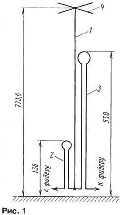
Encyclopedia of radio electronics and electrical engineering / HF antennas GP ON LOW FREQUENCY BANDS David Reid (PA40HBB/G80BZF) suggested an interesting shortened GP design for the 3m and 0m amateur bands. A detailed description of the antenna and the results of the experiments carried out by the author, which led to its creation, are available on his "home page" . With the kind consent of the author, we publish an abbreviated description of his antenna. It should be borne in mind that RAZNVV applied for a patent on this design, therefore it cannot be used for commercial purposes without the consent of the author. This, however, does not impose restrictions on the repetition of this antenna by shortwave operators for use on their amateur radio stations. Initially, the RAZNVV antenna was developed as a shortened GP for a range of 40 meters. Later it turned out that it can be adapted to work on a range of 80 meters (without changing the size of the main radiator and without degrading the characteristics of the antenna on a range of 40 meters). Schematically, this antenna is shown in Fig. 1 (dimensions - in cm). It consists of a main radiator (1), two "linear loads" (2 and 3 for 40 and 80 meters respectively) and a capacitive load (4).
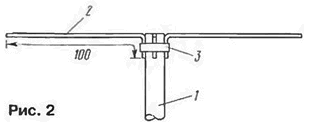
The main emitter is assembled from four pieces of duralumin pipes 2 m long each. To ensure their docking without additional elements (bushings), pipe sections of different diameters (30, 26, 22 and 18 mm, wall thickness 2 mm) were used, which were tightly inserted into each other to a depth of 88 mm. The resulting height of the main radiator is 773.6 cm. In the lower part, it must be isolated from the "ground". A piece of plastic water pipe of suitable diameter was used as a support insulator. Reliable fixation of the connection points of the individual elements of the emitter is provided with clamping clamps. The design of the capacitive load is shown in fig. 2. It consists of four duralumin strips (2) 100 cm long, 6 mm wide and 1 mm thick. One of the ends of each strip is bent at an angle of 90 * to a length of 50 mm (by clamping it in a vise and heating the bend with a gas burner). With the help of a clamping collar (3) they are attached to the main emitter, forming a horizontal "cross". To increase the mechanical stability of the "cross", the structure can be strengthened by installing a disk with a diameter of 150 mm in the center.
The purpose of the capacitive load is to reduce the quality factor of the emitter (i.e., expand the antenna bandwidth) and raise its input impedance to better match the 50-ohm feeder. So, the version of the antenna without a capacitive load on the 80-meter range had a bandwidth of only 180 kHz (in SWR - no more than 2), and the version with such a load - more than 300 kHz. To bring the total length of the radiator to a size that provides resonance on the corresponding amateur bands, the antenna uses the so-called "linear load" (linear loading). This term means that in order to reduce the physical dimensions of the antenna, instead of a lumped element (inductor), a change in the geometry of the emitter is used. With a "linear load" part of its web is bent and let along the main part of the emitter at a short distance. It is generally accepted that the shortening of the antenna by a "linear load" can be brought to a value of 40% without a noticeable deterioration in its parameters. The obvious advantage of this method in comparison with the use of an inductor is the simplicity of design and the absence of noticeable ohmic losses. The "line load" method is used by some companies in the design of directional antennas, and GAP also produces vertical antennas with a "line load". The total length of the "line load" for the GP is simply calculated: the total length of the antenna fabric (primary radiator plus "line load") should be equal to a quarter wavelength for the corresponding band. With a main radiator length of 773,6 cm, the lengths of the conductors included in the "linear load" in the antenna should have been 290,2 cm (range 40 meters) and 1309,7 cm (range 80 meters). Due to the presence of a capacitive load on the main radiator in this design, they should be slightly less than the given values. This shortening is not amenable to simple calculation, and in practice it is easier to select the elements of the "linear load" by taking them initially with a small margin and gradually shortening them until the antenna is tuned to the operating frequency. This is not difficult to do, since the operations are performed at the base of the antenna. In the author's version, the final length of the "line load" wires was 279 cm (minimum SWR at a frequency of 7050 kHz) and 1083,2 cm (minimum SWR at a frequency of 3600 kHz). In the manufacture of the "linear load" the author used an insulated copper wire with a diameter of 2.5 mm. Having cut off a piece of wire of the required length (with some margin for tuning), it is bent into a loop, which resembles a two-wire line, closed in the upper part by a conductor in the form of an incomplete ring (see Fig. 1). For fastening "linear loads" to the main radiator (1 in Fig. 3), dielectric spacers (2) are made. These spacers are screwed (5) directly to the main radiator. Wires (3). forming a "linear load", are passed through the holes in the spacers and, after adjustment, are fixed with epoxy glue (4). The length of the spacers is 50 mm (range 40 meters. 5 pcs.) and 120 mm (range 80 meters. 13 pcs.). They are evenly distributed along the length of the loop to ensure its reliable mechanical fixation. For fastening the loop rings, one spacer 120 mm long (range 40 meters) and one 320 mm long (range 80 meters) are made. "Linear loads" are placed on opposite sides of the main radiator.
The distance between the conductors of the "line" (dimension A in Fig. 3) for a range of 40 meters should be 40 mm. and for 80 meters -100 mm. The diameter of the ring "linear load" range of 40 meters -100 mm, and the range of 80 meters - 300 mm. One end of the loop of each "linear load" is connected to the lower end of the main radiator, and the remaining free ends - to the feeders. The antenna is fed either with separate coaxial cables, or with one cable, which is connected by the contacts of a high-frequency relay to "linear loads". An attempt to connect them simultaneously to the same cable was unsuccessful. On the 40 meters band, the characteristics of the antenna did not change, and on the 80 meters band, it simply stopped working. The dimensions of the antenna elements chosen by the author when fed through a coaxial cable with a wave impedance of 50 ohms ensured an SWR of no more than 1,5 within the entire range of 40 meters with a minimum SWR of 1,1 at a frequency of 7050 kHz. On 80 meters, the antenna was tuned to a minimum SWR (about 1.2) at a frequency of 3600 kHz. At the same time, in the frequency band 3500 ... 3800 kHz, the SWR did not exceed 2 (1,5 at a frequency of 3500 kHz; 1,6 at a frequency of 3700 kHz and 2 at a frequency of 3800 kHz). These data were obtained with a 50 sq. m. A direct comparison of a shortened antenna with a full-sized radiator on a range of 40 meters showed (according to the signal level correspondents and station reception) that they are almost identical. On a range of 80 meters, the shortening of the antenna already exceeds 60%. therefore, it is not necessary to talk about its very high efficiency. However, it also allows DX communications on this band. The author also tested the antenna with four wire counterweights 20 m long. They were "linearly loaded" like this. in order to "fit"1 into a square with dimensions of 10x10 m. At the same time, the SWR within the ranges of 40 and 80 meters increased slightly. DX contacts on 40 and 80 meters. TWO ALL-WAVE ANTENNAS Antennas that ensure the operation of a radio station on several amateur bands by introducing resistors into them continue to be popular with shortwaves despite the obvious drawback - reduced efficiency. There are several reasons for this popularity. First, these antennas usually have a very simple design - a frame of one form or another, in which a resistor is included. Secondly, due to their broadband they. as a rule, they do not require tuning, which significantly speeds up and simplifies the achievement of the final result - an antenna with which you can work on the air on several bands. As for the power loss in the resistor, it reaches 50%. On the one hand, the losses seem to be large, but on the other hand, a radio amateur (especially in urban areas) may not be able to install a more efficient multi-band antenna. Moreover, it is of this order that there can be non-obvious losses even in a single-band antenna system. A vivid example is the loss in a bad "ground" for antennas of the GP type (see, for example, the note "How many counterweights are needed" in Radio, 1999, No. 10. p. 59). It is difficult to measure these losses, so they simply prefer not to remember them. The classic version of the T2FD broadband tilting antenna with a resistor in the frame, which requires two masts 10 and 2 m high for installation and operates in the frequency band of 7 ... 35 MHz. described many times in the literature. An interesting horizontal version of such an antenna, requiring only one mast for installation and operating in the 10 ... . Finally, a vertical version of this antenna appeared. It was proposed by L. Novates (EA2CL) in the article "Otra vez con la antena T2FD" ("URE", 1998, p. 31,32). With a total height of about 7.5 m (see Fig. 4), this antenna provides operation in the 14 ... 30 MHz band, i.e., on all five high-frequency HF bands. The emitter (split loop vibrator) is made of two identical halves (1 and 2). They are made of duralumin pipes with a diameter of 25 mm and a wall thickness of 1 mm. Separate sections of pipes forming the emitter are interconnected by duralumin bushings (not shown in Fig. 4). On a free-standing wooden mast (3) 4.5 m high, the emitter is fixed with the help of crossbars: two - for the upper half of the emitter and two or three - for the lower one.
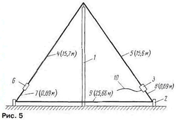
The terminating resistor R1 should have a power dissipation of approximately one third of the transmitter output power. Shown in fig. 4, the value of this resistor provides an input impedance of the antenna of 300 ohms, therefore, to power it through a coaxial cable with a characteristic impedance of 75 ohms, a broadband balun transformer with a transformation ratio of 1: 4 is required. If you use a cable with a characteristic impedance of 50 ohms. then the transformation ratio should be 1:6. When using a 500 ohm resistor, the input impedance of the antenna will be about 450 ohms. therefore, to power it with a coaxial cable with a wave impedance of 50 ohms, a balun transformer with a transformation ratio of 1: 9 is required. A variant of the design of such a transformer is given in the article mentioned above about the horizontal antenna T2FD. The balancing transformer is connected to points XX. The only small technical difficulty in the manufacture of the EA2CL antenna is the supply cable. To reduce pickups on its braid, the cable must be perpendicular to the antenna web over a length of several meters. Moreover, since in practice it is unrealistic to reduce these pickups to zero, it is necessary to create a choke for high-frequency currents on the cable (in the part where it is already vertical). The simplest solution is a small coil formed by several turns of the power cable. It should be noted that T2FD type antennas work quite well in the VHF band, and also usually have a good SWR even at frequencies below the cutoff. However, due to the small size of the emitter, its efficiency in this case, of course, deteriorates. The latter, however, does not exclude the possibility of using such an antenna for short-range communications. Antennas with a load resistor are also produced by some companies. So the company Barker & Williamson produces the AC-1.8-30 antenna, which operates in the frequency band 1,8 ... 30 MHz and can, in principle, be installed on the roof of a residential building (not a tower type). To install such an antenna (Fig. 5), only one (1) 10,7 m high non-metallic mast is required. In amateur radio literature (Pat Hawker, "Technical Topics", "Radio Communication", 1996, June. p. 71, 72) there is a dispute about that. how to call it: either "Vertical Half Rhombic" (VHR - Vertical Half Rhombic), or "Loaded Pyramid". To this dispute, we can add that the antenna also resembles a heavily deformed T2FD. In any case, it works well, but what to call it is a secondary question.
In addition to the mast (1), two more racks (2) 0.9 m high are needed to install the antenna. The antenna is fed through a coaxial cable (10) and a broadband balancing transformer (3) with a transformation ratio of 1:9. The radiating part of the antenna - conductors forming a half-rhombus (4 and 5). The load resistor (6) has a resistance of 450 ohms. The requirements for it in terms of power dissipation are the same as in the T2FD antenna. The conductors closing the frame (7, 8 and 9) form a counterweight for the semi-rhombus. The height of the conductor suspension (9) above the surface is only 5 cm. It should be noted that with such a suspension height, the racks (2) can, apparently, have a noticeably lower height. All conductors used copper wire with a diameter of 2 mm. Needless to say, the load resistor and balancing-matching transformer must be reliably protected from atmospheric moisture. This applies to both the T2FD antenna and the VHR antenna. Using the ideas behind the VHR antenna. it is possible, apparently, to create a very compact device for a narrower band of operating frequencies (for example, 3.5 ... 30 MHz or 7 ... 30 MHz) and, accordingly, a smaller number of amateur bands.
Machine for thinning flowers in gardens
02.05.2024 Advanced Infrared Microscope
02.05.2024 Air trap for insects
01.05.2024
▪ The most powerful laser in the world ▪ Smartphones ZTE Nubia Z5S and Z5S mini ▪ Butterfly saves not the pattern of eyes on the wings ▪ Lighting LEDs with an efficiency of 135 lm/W ▪ Innovative orbital housing concept from Airbus
▪ section of the site Fundamentals of safe life (OBZhD). Article selection ▪ article Sweet woman. Popular expression ▪ article Why is the pronoun I capitalized only in English? Detailed answer ▪ article Deputy Head of AHO. Job description ▪ Telekinesis article. Focus secret
Home page | Library | Articles | Website map | Site Reviews www.diagram.com.ua |


 Arabic
 Bengali
 Chinese
 English
 French
 German
 Hebrew
 Hindi
Hindi Italian
 Japanese
 Korean
 Malay
Malay Polish
 Portuguese
 Spanish
 Turkish
 Ukrainian
 Vietnamese


 Leave your comment on this article: