|
|
ENCYCLOPEDIA OF RADIO ELECTRONICS AND ELECTRICAL ENGINEERING Measuring bridge generator. Encyclopedia of radio electronics and electrical engineering
Encyclopedia of radio electronics and electrical engineering / Antennas. Measurements, adjustment, coordination To establish antennas using a measuring bridge, you need a stable RF signal source operating in the amateur bands and having an output power of at least 100 mW. It is not always convenient to use a transceiver for these purposes, especially if measurements need to be made on the roof (directly near the antenna). A diagram of such a generator is shown in the figure.
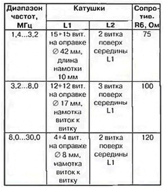
The diagram published in the Radio magazine (1999, No. 5, p. 59) was taken as a basis. The generator covers the frequency band from 1,4 to 30 MHz in three subbands: 1,4...3,2 MHz. 3,2...8,0 MHz, 8,0...30,0 MHz. In the first subrange, its output power (measured at a load of 50 ohms) is at least 400 mW, in the second range - at least 300 mW, in the third range - from 150 mW at 30,0 MHz to 200 mW at 8 MHz. When the antenna is connected, the frequency drift of the generator is no more than 5 kHz in the first range, no more than 15 kHz in the second and no more than 30 kHz in the third. This allows you to use this generator to tune narrowband antennas, using a simple mechanical scale in its design, and be sure of its true readings. As can be seen from the figure, the circuit consists of a master oscillator based on transistors VT1, VT2 and a linear power amplifier based on transistor VT3. High results of the master oscillator were obtained with transistors of the KT630A type. The required range of the generator is selected by switch SA1. The switching of the ranges in the diagram is shown in a simplified way, for only one range, in order to avoid cluttering the figure. The master oscillator is powered by a stabilized voltage of +5 V. The same voltage is also applied to the base circuit of the transistor VT3 of the power amplifier. Such a construction of the power circuit made it possible to maintain a stable generation frequency, ranging from a voltage of +8 V to the maximum value of the generator supply voltage of +15 V. The A1 microcircuit is used without a heat sink. The generator is assembled in a case measuring 160x90x100 mm from double-sided foil fiberglass. For frequency stability, its design should be as rigid as possible. The generator was mounted by a hinged method (on patches), on the rear wall of the device. The design data of the coils, as well as the initial value of the resistance R6 for each of the subranges, are given in the table.
All coils are wound with PEV-2 wire 0,5 mm. Transformer T1 is wound on a ferrite ring magnetic circuit of the 600NN brand, size K10x6x5 mm. Its winding consists of 2x10 turns of PEV-2 wire 0,3 mm. Throttle L3 - standard type DM-0,2. As C1, an air-dielectric variable capacitor from an old receiver and a double-delayed vernier was used. Switch SA1 - ceramic biscuit type PKG ZPZN. High-frequency connector - СР50-73ФВ. Setting up the generator is not difficult. If possible, transistors VT1 and VT2 must be used with the same base current transfer coefficients. With an oscilloscope or an RF voltmeter, you need to make sure that the amplitudes of the high-frequency voltage on the collectors of these transistors are equal. If the signal levels differ by more than 30%, then it is desirable to select transistors VT1 and VT2. If necessary, select resistors R1 and R7, R2 and R5, achieving a sinusoidal output signal on all ranges. By selecting the resistor R8, the collector current of the transistor VT3 is set within 100 ... 150 mA. This transistor is mounted on a 40x40x4 mm aluminum heat sink. Resistor R6 is selected separately for each range. The greater the resistance of this resistor, the higher the frequency stability and the lower the output power of the generator. The boundaries of the ranges of the generator are set by compression-stretching of the extreme turns of the coil L1. It must be done symmetrically. The generator is powered by an external +12 V voltage source. It can be either dry batteries or accumulators. The current consumed by the generator is about 200 mA. Author: I. Grigorov (RK3ZK)
Artificial leather for touch emulation
15.04.2024 Petgugu Global cat litter
15.04.2024 The attractiveness of caring men
14.04.2024
▪ Absolutely unbreakable screen for gadgets ▪ Antibiotics to fight superbugs ▪ ERхххххH - FANSO lithium batteries ▪ Combat modular laser has been tested ▪ Technology for remanufacturing old engines
▪ section of the site Cultivated and wild plants. Article selection ▪ article Using Visual and Auditory Orientation Markers. Basics of safe life ▪ article hunter. Job description
Home page | Library | Articles | Website map | Site Reviews www.diagram.com.ua |


 Arabic
 Bengali
 Chinese
 English
 French
 German
 Hebrew
 Hindi
Hindi Italian
 Japanese
 Korean
 Malay
Malay Polish
 Portuguese
 Spanish
 Turkish
 Ukrainian
 Vietnamese


 Leave your comment on this article: