VHF loop antenna made of coaxial cable. Encyclopedia of radio electronics and electrical engineering

Encyclopedia of radio electronics and electrical engineering / Antennas. Measurements, adjustment, coordination
 Comments on the article
Loop antennas are sometimes made from the braid of a coaxial cable. One of the options for such an antenna is in the second part of my book "HF and VHF Antennas". It has not only many advantages (cheapness, wide bandwidth, speed of manufacture), but also a minus.
The input impedance of a round or square frame is about 120 ohms, and the feeder usually has a characteristic impedance of 50 ohms. There are only two options in this case. You can stretch the frame into a narrow rectangle with an aspect ratio of 1:2. Only in this form does it have an input impedance of 50 ohms. However, this solution is inconvenient from a constructive point of view. And with a more familiar and convenient frame shape (circle, square), a matching device must be used for matching. This also does not decorate the design due to the need to introduce additional elements.
The article describes a convenient constructive version of the frame and its matching device (for an input impedance of 50 ohms) from one single piece of coaxial cable with a characteristic impedance of 75 ohms.
The idea is to use a piece of coaxial cable with a characteristic impedance of 4 ohms as a λ/75 matching device, which transforms 120 ohms into 50 ohms. And from the same cable to make the antenna frame itself.
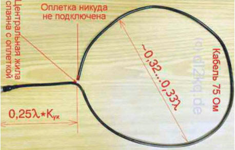
Fig. 1
The resulting design is shown in Fig. 1. The antenna is made from a piece of 75 ohm cable (for example, RG-59, as in this figure). Its length is chosen from the following considerations.
The electrical perimeter of the frame itself should be 1,03 ... 1,05λ - on VHF, increased values of the elongation coefficient are required due to the large (relative to the wavelength) diameter of the frame conductor. But in our case, it is covered on top with a rather thick layer of plastic (external insulation), which has a noticeable shortening effect and compensates for the elongation factor. Therefore, the physical perimeter of the frame from the cable is about 1λ.
Small inaccuracies (for example, due to the spread of the dielectric constant of the cable insulation) are not terrible. The bandwidth of the antenna will be large, and this forgives small errors in its manufacture.
The electrical length of the matching segment should be R/4. And the physical one - in the shortening coefficient Cook (internal, from the cable passport) times less. Total length of the cable section
equal to the sum of the above lengths. For example, for RG-59, which has a velocity factor of 0,66, the total length will be 1λ+0,66λ/4=1,165λ.
This antenna is made like this. A piece of coaxial cable with a characteristic impedance of 75 ohms is cut off - its length should be slightly larger than the value calculated above. At its upper end, the braid is cut to a length of several millimeters, and the central conductor is exposed.
Exactly one wavelength is retreated from the split upper end, and in this place the outer insulation of the cable is carefully opened without damaging the braid, so that its fragment is available for soldering. At this point, the center conductor of the upper end is soldered to the braid, and this connection is waterproofed (for example, with hot glue). The resulting loop is shaped into a circle or square.
The lower end of the cable is connected either directly to the antenna socket of the transceiver with an output impedance of 50 ohms, or to the main feeder with a characteristic impedance of 50 ohms.
According to the recipe described above, a measuring antenna for a frequency of 290 MHz (λ = 1,03 m) was made from a piece of RG-59 coaxial cable 1,2 m long (1,165λ). The dependence of the SWR of this antenna on frequency is shown in fig. 2.
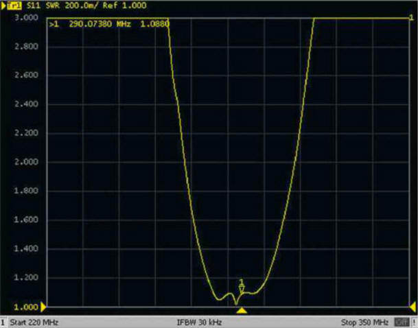
Fig. 2
The band in terms of SWR <1,5 turned out to be 30 MHz. This means that similar antennas with a large margin and low SWR will cover the entire amateur bands 144 or 430 MHz.
The manufacture of the described VHF loop antennas (amateur VHF bands, Wi-Fi, GPS, PMR, etc.) will require only half an hour of time and small costs for the purchase of a cable, connector and hot melt adhesive.
Author: Igor Goncharenko
 See other articles Section Antennas. Measurements, adjustment, coordination.
Read and write useful comments on this article.
<< Back
 Latest news of science and technology, new electronics:
A New Way to Control and Manipulate Optical Signals
05.05.2024
The modern world of science and technology is developing rapidly, and every day new methods and technologies appear that open up new prospects for us in various fields. One such innovation is the development by German scientists of a new way to control optical signals, which could lead to significant progress in the field of photonics. Recent research has allowed German scientists to create a tunable waveplate inside a fused silica waveguide. This method, based on the use of a liquid crystal layer, allows one to effectively change the polarization of light passing through a waveguide. This technological breakthrough opens up new prospects for the development of compact and efficient photonic devices capable of processing large volumes of data. The electro-optical control of polarization provided by the new method could provide the basis for a new class of integrated photonic devices. This opens up great opportunities for ... >>
Primium Seneca keyboard
05.05.2024
Keyboards are an integral part of our daily computer work. However, one of the main problems that users face is noise, especially in the case of premium models. But with the new Seneca keyboard from Norbauer & Co, that may change. Seneca is not just a keyboard, it is the result of five years of development work to create the ideal device. Every aspect of this keyboard, from acoustic properties to mechanical characteristics, has been carefully considered and balanced. One of the key features of Seneca is its silent stabilizers, which solve the noise problem common to many keyboards. In addition, the keyboard supports various key widths, making it convenient for any user. Although Seneca is not yet available for purchase, it is scheduled for release in late summer. Norbauer & Co's Seneca represents new standards in keyboard design. Her ... >>
The world's tallest astronomical observatory opened
04.05.2024
Exploring space and its mysteries is a task that attracts the attention of astronomers from all over the world. In the fresh air of the high mountains, far from city light pollution, the stars and planets reveal their secrets with greater clarity. A new page is opening in the history of astronomy with the opening of the world's highest astronomical observatory - the Atacama Observatory of the University of Tokyo. The Atacama Observatory, located at an altitude of 5640 meters above sea level, opens up new opportunities for astronomers in the study of space. This site has become the highest location for a ground-based telescope, providing researchers with a unique tool for studying infrared waves in the Universe. Although the high altitude location provides clearer skies and less interference from the atmosphere, building an observatory on a high mountain poses enormous difficulties and challenges. However, despite the difficulties, the new observatory opens up broad research prospects for astronomers. ... >>
| Random news from the Archive New Panasonic DECT phones
08.06.2014
Panasonic has introduced a new series of cordless phones. The KX-TGH210RU, KX-TGH212RU, KX-TGH220RU, and KX-TGH222RU have a compact design and backlit keyboard and screen.
The KX-TGHxxxRU series phones have advanced features such as background noise reduction. It allows you to minimize the noise that occurs on the side of the other subscriber and makes the voice of the interlocutor clearer.
Another feature of the new series is the ability to search for any object using a tube and a key fob, which can be purchased separately. While searching, the devices emit a sound signal, and the display of the phone shows the distance to the searched object. Up to 4 key fobs can be used at the same time, and each can be assigned a personal name.
Also, all models have an intelligent function that provides quick access to certain phone features that are most relevant to the user at a particular moment.
In addition, the KX-TGHxxxRU series phones are equipped with useful options such as night mode, which allows you to turn off the ringer on the handset for a certain period of time. At the same time, you can set a list of numbers on your phone that are not covered by night mode. Other useful options include a backup power supply that provides temporary operation of the base unit due to the handset batteries, an eco mode and a baby monitor. In addition, the KX-TGH220RU and KX-TGH222RU versions are equipped with a digital answering machine that provides up to 40 minutes of recording.
All models of the series have a built-in address book with a capacity of up to 200 numbers, a set of polyphonic ringtones and the ability to connect up to 6 handsets. The phone's talk time is up to 14 hours and standby time is up to 250 hours.
|
Other interesting news:
▪ The bus recognizes the pedestrian
▪ The chamber is smaller than the thickness of a human hair
▪ Transcend High Endurance microSD cards
▪ Light radar on a microchip
▪ Flash drive 16 GB
News feed of science and technology, new electronics
 Interesting materials of the Free Technical Library:
▪ section of the site for the Builder, home craftsman. Selection of articles
▪ Article Safety razor. History of invention and production
▪ How does a sundial tell time? Detailed answer
▪ article diathesis. Health care
▪ article Power supply project. Encyclopedia of radio electronics and electrical engineering
▪ article Change in the resistance of metals with the introduction of impurities. Encyclopedia of radio electronics and electrical engineering
Leave your comment on this article:
 All languages of this page
Home page | Library | Articles | Website map | Site Reviews

www.diagram.com.ua
2000-2024


 Arabic
 Bengali
 Chinese
 English
 French
 German
 Hebrew
 Hindi
Hindi Italian
 Japanese
 Korean
 Malay
Malay Polish
 Portuguese
 Spanish
 Turkish
 Ukrainian
 Vietnamese