|
|


 Arabic
 Bengali
 Chinese
 English
 French
 German
 Hebrew
 Hindi
Hindi Italian
 Japanese
 Korean
 Malay
Malay Polish
 Portuguese
 Spanish
 Turkish
 Ukrainian
 Vietnamese
|
ENCYCLOPEDIA OF RADIO ELECTRONICS AND ELECTRICAL ENGINEERING Antenna equivalent with power indicator. Encyclopedia of radio electronics and electrical engineering
Encyclopedia of radio electronics and electrical engineering / Antennas. Measurements, adjustment, coordination To set up a homemade shortwave power amplifier or transceiver, a radio amateur needs, among other measuring instruments, an antenna equivalent and a simple output power indicator (aka a wattmeter). Since purchasing branded instruments is not cheap, some simple measuring devices can be made independently. Moreover, if we combine structurally the equivalent of an antenna with a power indicator in one housing, this will save space in the amateur radio "shack" and eliminate additional connecting wires. The output power indicator proposed in the article (Fig. 1) consists of an antenna equivalent, which is made on a non-inductive microwave resistor R1 RFP250N50TC from Anaren Microwave, a voltage divider on resistors R2, R3 and capacitor C1 and a simple RF voltmeter AC on the elements VD1, C1, C2, R4, PA1. Capacitor C1 performs frequency correction in the HF ranges and sets the uniformity of the frequency response of the voltmeter. The author has this capacitor homemade. It is made of a plate of fiberglass foiled on both sides with dimensions of 7x15 mm and a thickness of 1,5 mm. Its capacitance was selected experimentally by a gradual decrease on both sides of the foil areas. As a result, the dimensions of its plates were reduced to about 5x7 mm, and the capacitance measured by the MAS LC meter was about 0,7 pF. Switch SA1 determines the limits of power measurement - 200 or 500 W by connecting shunt R5 in parallel with the measuring device.
For long tuning sessions at the maximum output power of the amplifier, the design of the pointer provides for forced airflow of the antenna equivalent - resistor R1. The blower is controlled by a thermal switch (Fig. 2). When power is applied, the motor M1 rotates at a reduced speed at the minimum voltage for a sure start. This voltage is determined by the stabilizer DA1 and the diode VD4. When the heat sink temperature rises to +55 оWith the resistance of the thermistor RK1 decreases, the transistor VT1 opens and relay K1 is activated. The motor M1 receives the full supply voltage through the diodes VD2, VD3. These two diodes connected in series reduce the fan supply voltage from 13,8 to 12,6 V. At the same time, the HL1 LED lights up, signaling a noticeable heating of the antenna equivalent and that it may be necessary to pause the transmission.
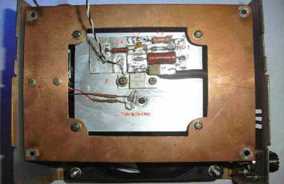
Most of the indicator parts are mounted on a board made of foil fiberglass 1,5 mm thick (Fig. 3). Mounting - hinged on the "patch". Resistor R1 is fixed (through KPT-8 thermal paste) on a ribbed heat sink measuring 90x65x35 mm from the Intel P4 series microprocessor cooling system.
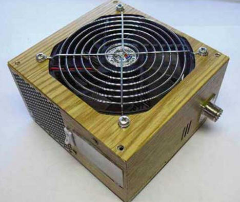
The RA1 device is any microammeter with a large scale and a total deflection current of 100 μA. Miniature CMH incandescent lamps are mounted in the instrument to illuminate the scale. Connector XW1 - SO239. The indicator scale (I deliberately do not call the design a "device") is graduated in watts. Preliminary calibration was carried out at a frequency of 50 Hz using LATR. Then it was checked in the middle and end of the scale with a VK7-9 RF voltmeter with a control signal from the output of the Kenwood TS-570 transceiver. The scale turned out, as expected, close to logarithmic. I believe that a reading error of 10 ... 20 W at a power measurement limit of 500 W in amateur radio practice is quite acceptable for most cases of using the pointer. The resistance of the shunt resistor R5 is selected experimentally in the process of setting up the device. Its required rating is determined by the characteristics of the RA1 microammeter used. The 200 W scale is calibrated in the same way. The thermal relay is mounted on a breadboard. Thermistor RK1 - MMT-1, is installed on the heat sink of the antenna equivalent through the KPT-8 thermal paste. Relay K1 - RES49 for an operating voltage of 12 V. LED HL1 - with a diameter of 5 ... 6 mm of any type, red glow. The M1 electric motor is a standard cooler with dimensions of 120x120 mm from a computer power supply unit of the ATX form factor. The whole structure is assembled in the same case (Fig. 4).
The device is powered by the transceiver's power supply and consumes no more than 300 mA. Author: Dmitry Inozemtsev (UA1ZKI)
The existence of an entropy rule for quantum entanglement has been proven
09.05.2024 Mini air conditioner Sony Reon Pocket 5
09.05.2024 Energy from space for Starship
08.05.2024
▪ Multitasking reduces brain productivity ▪ Nanohousing for sun-loving bacteria ▪ Refractory clay supercapacitor ▪ Unexpected properties of yogurt ▪ A new way to control the speed of light
▪ site section Infrared technology. Article selection ▪ article Dove of Peace. Popular expression ▪ article Why is a computer program update called a patch? Detailed answer ▪ article Tuberous Ulluko. Legends, cultivation, methods of application ▪ Article Experience with extinguished candle. physical experiment
Home page | Library | Articles | Website map | Site Reviews
www.diagram.com.ua |


 Leave your comment on this article: