|
|


 Arabic
 Bengali
 Chinese
 English
 French
 German
 Hebrew
 Hindi
Hindi Italian
 Japanese
 Korean
 Malay
Malay Polish
 Portuguese
 Spanish
 Turkish
 Ukrainian
 Vietnamese
|
ENCYCLOPEDIA OF RADIO ELECTRONICS AND ELECTRICAL ENGINEERING Shortened antenna for 160 meters. Encyclopedia of radio electronics and electrical engineering
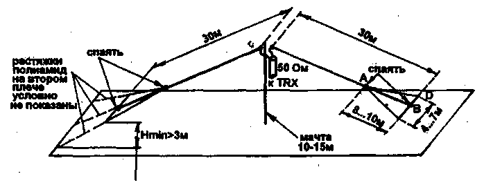
Encyclopedia of radio electronics and electrical engineering / HF antennas The dimensions of full-sized antennas at 160 m encourage us to look for acceptable solutions for shortening them. The author, for example, was prompted to do this by the sad circumstance that a full-size Inverted V dipole on a mast of reasonable height (12 m) does not fit into the dimensions of the roof of a typical panel house. Rather, it fits, but in such a way that nothing good can be expected from such placement - the last few meters (5-7 m) on each side of the dipole practically lie on the roof. The height of these extreme segments above the roof is 0,5 ... 1,5 m, which is bad for at least two reasons: 1. A large voltage develops at the ends of the dipole, which, with serious power, can lead to accidents if people accidentally touch the antenna that is transmitting; 2. As a rule, on any roof, various wires run along it at a height of about 2 m - lighting, elevator cables, radio broadcasts, etc., which successfully absorb everything that is emitted by those parts of the antenna that are located below these wires. By the way, the same circumstance is the reason for the unsatisfactory operation of various wire antennas hung between multi-storey buildings and located entirely below the roof level, since the radiation at small angles to the horizon, which is necessary for operation on DX paths, is especially strongly absorbed. In addition, such placement may cause TVI. Thus, it is necessary that the ends of the antenna be at least 3 m above the roof. If you have the opportunity to put two additional 3 m high masts on the edges of the roof, then do so and you can stop reading this article.
If this is not possible, an acceptable option is shown in Fig. 1. With practically no decrease in efficiency, it was possible to reduce the total length of the canvas from 76 to 60 m, which made it possible to raise the lower edges to a height of 3 m when attaching polyamide stretch marks to the roof railing. The shortening was achieved due to capacitive loads at the ends of the dipole, made in the form of "to catch the oars". The performance of capacitive loads with a gradual increase in the width of the vibrator arms (without inhomogeneities) provides a smooth change in wave impedance without jumps, better matching of the antenna with free space, and as a result, higher efficiency compared to the classic version of the capacitive load - a disk or a set of radial wires at the end of a thin vibrator. The dimensions of the capacitive loads in Fig. 1 should be considered as indicative only, since during the tuning process they can seriously change. For ease of manufacture and tuning of the antenna, it is necessary that the mast be securely fastened with braces and stand firmly with loose vibrators. In addition, ensure that the soldering iron can work, if not on the entire roof, then at least at the base of the mast. It is convenient to follow the following installation and adjustment procedure. 1. A mast with a power cable pre-attached to it and two vibrator arms 1 m long each, made of copper wire or Antenna cord with a diameter of 30 ... 2,5 mm, is raised and fixed with braces (not shown in Fig. 4). The top knot is made in the same way as a conventional full-size antenna. 2. Stepping back from the hanging edge of the vibrator 10 m, two additional wires about 14 m long each are soldered to it (point A), and the ends of these wires are connected by soldering to the end of the vibrator (chute B). Additional wires carry a small mechanical load and can be 1,0...2,0 mm in diameter (non-critical). After that, stretch marks from a polyamide cord capacitive load give the shape shown in Fig.1. There is no need to maintain the correct shape of the triangles and place all three wires in the same plane - do it as it is more convenient for local conditions, focusing on the dimensions indicated in Fig. 1. The same is done with the second half of the vibrator, which has the same dimensions as the first. 3. Roughly (with an accuracy of approximately ± 100 kHz) adjust the resonant frequency of the antenna (the frequency at which a minimum SWR is observed) by changing the length of the additional wires and re-soldering points B, as well as fastening points C and D simultaneously at both arms of the vibrator. 4. If, when performing step 3, it is not possible to achieve the desired result, you will have to change the size of A-B. Its increase leads to a decrease in the resonant frequency, shortening - to an increase. 5. To fine-tune the resonant frequency (within ± 100 kHz), without changing the length of the additional wires, move the attachment points of the side braces C and D. In this case, the shape of capacitive loads from triangular can become closer to rhombic, which is quite acceptable. At this stage, it is necessary to achieve not only the given resonant frequency, but also the minimum SWR at it. To do this, you may have to find points C and D differently on the left and right half of the vibrator. This antenna has the following features: - the reduced sizes and big height of a suspension bracket of edges; - capacitive shortening leads to the smallest decrease in efficiency among all shortening methods; - concentrated add-on elements are not required; - the adjustment is very convenient and is carried out at the bottom - at the level of the roof, that is, no work is required on the mast. The tuned antenna has an SWR at resonance < 1,2 and a bandwidth of 90 kHz at SWR < 2. Over 1,5 summer months, more than 80 DXCC countries from all (except Australia) continents have worked with this antenna. Publication: N. Bolshakov, rf.atnn.ru
Machine for thinning flowers in gardens
02.05.2024 Advanced Infrared Microscope
02.05.2024 Air trap for insects
01.05.2024
▪ Improving the efficiency of MRAM memory ▪ Charging station Bluetti AC180
▪ section of the site The most important scientific discoveries. Article selection ▪ article Skryabin Alexander Nikolaevich. Famous aphorisms ▪ article What type of communication do adult cats use only to attract a person? Detailed answer ▪ article Upholsterer. Standard instruction on labor protection
Home page | Library | Articles | Website map | Site Reviews
www.diagram.com.ua |

 Leave your comment on this article: