|
|


 Arabic
 Bengali
 Chinese
 English
 French
 German
 Hebrew
 Hindi
Hindi Italian
 Japanese
 Korean
 Malay
Malay Polish
 Portuguese
 Spanish
 Turkish
 Ukrainian
 Vietnamese
|
ENCYCLOPEDIA OF RADIO ELECTRONICS AND ELECTRICAL ENGINEERING Small-sized fox antenna 144 MHz. Encyclopedia of radio electronics and electrical engineering
Encyclopedia of radio electronics and electrical engineering / VHF antennas Even before publication, in the process of discussion among radio athletes, an article by a specialist in antenna technology, candidate of technical sciences K.P. Kharchenko, caused controversy. Master of sports of international class, multiple winner of competitions of various scales (including European championships), resident of Gorky A.I. Grechikhin called the idea underlying the proposed design "very interesting and original." He also noted the simplicity of the device. No less experienced athlete, Candidate of Physical and Mathematical Sciences, Muscovite VN Verkhoturov believes that the creation of an antenna that provides the possibility of direction finding to a minimum "could be of serious interest to athletes." It also seems to us that this small-sized antenna can have a great advantage over a rather bulky "wave channel" - after all, often a "hunter" in search of a "fox" has to literally wade through dense thickets. However, both athletes (the master of sports from Sverdlovsk A.S. Partin joins them) criticized the design. So, they expressed doubts about the advisability of placing the antenna on the athlete’s head - it’s not very convenient, specifying the direction during movement, to rotate the head all the time (but it’s possible, apparently, to develop a different search technique?). In addition, according to the rules of the competition, they say, not only vertical polarization, for which the antenna is designed, but also horizontal polarization is possible (well, it's quite simple - just place the vibrators horizontally). In short, almost all critical statements were counterargued. And, most importantly, if desired, the design of the antenna can be changed by adapting it to be carried in the hands. More serious concerns are related to the inevitable impact on the parameters of the system (in particular, on the symmetry) of changing capacitance with respect to the ground, with a low effective height of the antenna, with its sensitivity to reflected signals. .Only practical operation can dispel these fears. The editors share the opinion of A. I. Grechikhin that this antenna is "an interesting proposal that can be applied to development." We hope that the published article will be useful for amateur radio athletes. Fox hunters must have at their disposal equipment that allows them to select the direction to the "fox". This problem is solved by antennas in conjunction with the receiving device. There are two ways to construct such antennas. In the first case, the antenna must have a pronounced unidirectional pattern, and the given direction is selected according to the maximum received signal by comparing signals from neighboring directions and choosing the desired one. In the second case, there is one deep minimum in the antenna pattern. Here, too, the desired direction is determined by comparison and selection, but already by the signal minimum. If we analyze both options, then the second one seems theoretically more preferable, if only because in the first case, to obtain a narrow radiation pattern, a "large" antenna is needed, as a rule, commensurate with the wavelength. In addition, it is more difficult to determine the direction to the "fox" as you approach it by the maximum signal than by the minimum. This article proposes a variant of building a small antenna with a pronounced minimum in the radiation pattern. A constructive solution of the receiving device is also proposed, which allows the athlete to free his hands, which will obviously increase his maneuverability. In order to understand the principle of operation of the antenna, let's turn to Fig. 1, a (in the text). It shows a segment of a homogeneous long line, which includes two conditional identical generators G1 and G2 of high-frequency oscillations. O is the middle of the line, U is the voltage distribution curve along the line. If the generators are in-phase, then the maximum (voltage antinode) falls in the middle of the line. If the phase of the oscillations of the generator G2 lags behind the phase of the oscillations of the generator G1, then the voltage distribution curve in the line will shift by some angle j, as shown in Fig. 1b. If, on the contrary, the phase of the oscillations of the generator G2 is ahead of the phase of the oscillations of the generator G1, then the distribution curve will shift in the opposite direction, as shown in Fig. 1c. If we agree to determine the voltage in the line by turning on the device at points 3-4, then we can see that |U3|> &|U1|, and U2=0.
As the considered conditional generators, two identical antennas, for example, dipoles (Fig. 1, d), can act. In this case, the phases of oscillations in the line will depend on the direction of arrival of radio waves. In Fig. 1d, the arrows show three directions: I - radio waves arrive at both antennas simultaneously; II - in the path of propagation of radio waves, antenna 1 first stands, and behind it antenna 2; III - on the contrary, antenna 2 is in front, and 1 is behind. Measuring the same instrument in the half-wave length line of the voltage in the section spaced from the antenna 1 at a distance j in electrical degrees, we obtain, respectively, all the cases considered above. Thus, without knowing in advance the direction of arrival of radio waves, you can find it by rotating the system of two antennas until the device at points 3-4 shows a minimum voltage in the line. In this case, obviously, the direction of propagation of radio waves coincides with the direction II. The radiation pattern of such an antenna-feeder device will be of the cardioid type. Assuming that the "fox" signal is distinguishable at the noise level of the receiver, when the antenna is turned to it at a certain angle relative to the zero direction, it is possible to find that dead zone, within which one of the directions is probably the desired one. As you get closer to the transmitter (with increasing radiation level), the dead zone will decrease, and the desired direction will be determined more accurately. It is possible to implement the described method of constructing an antenna and a receiver, using as an example the constructive variant shown in Fig. 2. Here is a general view of the device, made in the form of a headset.
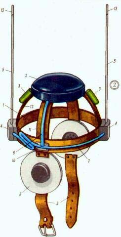
It is based on a metal hoop 1 and arcs - transverse 11 and longitudinal 12. A metal case 2 for the receiver is also installed in the area where the arcs intersect. If the dimensions of the batteries cannot be placed inside the receiver case, then they are fixed on the longitudinal arc 12 (two batteries - 3). The load of the receiver is phones 8, framed in soft, soundproof pads, to which straps 9 are sewn to secure the headset under the chin. Phones through spacers are fixed at the ends of the transverse arc 11. On the frontal and occipital parts of the hoop 1, two antenna insulators 4 are placed and rigidly fastened to it. Antenna insulators fix antennas 5 of the pin type. At the ends of the antennas there are adjusting bushings 13. The power terminals of both antennas are connected by line 7 (line l in Fig. 1, d), line 6 connects the receiver input to line 7 through a tee 10 (points 3 and 4 in Fig. 1, d). The receiver must have a high input impedance (so as not to shunt the line). A longer segment of the line 7 in a folded (zigzag) form is laid on the hoop 1. In the manufacture of the structure, one should strive for maximum symmetry about the vertical axis passing through the center of the hoop. Failure to comply with this requirement will result in a distortion of the symmetry in the radiation pattern and errors in determining the direction.
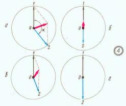
On fig. 3 shows the dimensions of the elements that make up the basis of the headset. The size S is important only in that it determines the distance in fractions of a wavelength in line 7 from the frontal antenna to the point where line 6 is switched on. The geometric size of line segment 7 is determined as l1=S/2e where e is the velocity factor. For a coaxial cable with polyethylene filling, e = 1,51-1,52, therefore, for our option l1=70 mm. The total length of the line is half the average wavelength, taking into account the shortening of the wave in the cable. With lav=2,07m l=680 mm. If you add to the total length l along the same length of 80 mm on each side, this will increase l1 up to 150 mm for more convenient placement of the tee 10 at the intersection of the arcs. If the antenna-feeder device could be made without errors and strictly symmetrical electrically, the production would be completed. However, this cannot be done immediately, and at the points where line b is connected to line 7, the signal voltages from the antennas are either not equal in amplitude, or the phase shift between them is not equal to 180 °, when the radio waves come from the "zero" direction. Both that, and another does not allow to receive the resulting tension equal to zero. This is illustrated in Fig. 4. Here the vectors 1 and. 2 depict the voltages coming from the first and second antennas, respectively, the angle a is the phase shift. The resulting voltage is a red vector. On fig. 4, and voltages 1 and 2 are equal in amplitude, but not strictly out of phase, in fig. 4, b, the voltages are antiphase, but their amplitudes are not equal to each other, in fig. 4, the voltages are not out of phase and are not equal in amplitude. At all these positions, the resulting voltage is different from zero, and only in Fig. 4, d it satisfies our requirements.
It is not so easy to provide both of these conditions in a real antenna-feeder device, since when, for example, the length of the antenna changes, both the phase and the amplitude of the signal coming from it change simultaneously. At least one more adjustment is needed, providing a change in only the phase (or only the amplitude). Only the phase can be changed by expanding the axes of the vibrators relative to each other (by changing the size S) or by changing the point of connection of line 6 to line 7. How the connection point can be structurally changed is shown in fig. 5 and 6.
The total length of the line (over the braid) is 840 mm. The ends Dl, the same on both sides, are necessary for embedding in insulators. Here 1 is the central conductor of the cable, 2 is the protruding part of its polyethylene insulation, 3 is a bracket covering the braid and soldered to it (it serves as a contact and a braid retainer). These brackets must be soldered to the headband of the headset. At a distance of 150 mm from the end of bracket 3 adjacent to the frontal antenna, a cut should be made, exposing conductor 1 for about 50 mm. The cable sheath in the section also needs to be sealed into brackets 3 and soldered to the copper (brass) plate 4. This section will later serve as a line segment for phase compensation.
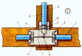
On fig. 6 shows a plot; headset that hosts this node. Here 12 is a segment of the transverse arc, 7 is a segment of the hoop. The hoop and the transverse arc are fastened to each other and have electrical contact. Plate 4 is attached to the hoop with rivets 9 so that there is a gap between it and the hoop. Cable 5 is laid along the hoop. The braid of the cable end of the line 6 is covered by the bracket 11 fixed on the plate 10, the cable 6 is laid on the transverse arc 12 and the second end is connected to the receiver. The plate 10 is tightly inserted into the slot formed by parts 4 and 7, the central conductors 1 and 8 are connected. The protruding part of the polyethylene insulation 13 protects the conductor 8 from a short circuit with the plate 4. By moving the plate 10 along the slot, and with it the conductor 8, it is possible to change the switching point of the line 6, thus selecting the desired phase. The adjustment is carried out in several steps, by the method of successive approximations. By changing the length of the vibrator of one of the antennas, they try to choose such a position for switching on the lines so that the signal at the receiver input is zero (or has a sharp minimum). In this case, the headset must be properly oriented towards the transmitter. Line conductors should not be touched at the time of measurement, so that there are no violations of the electrical symmetry of the system. Upon reaching the result, you need to fix the obtained dimensions and positions. The open parts of the lines (section) must be closed with a lid (it can be dielectric) and all cable segments should be attached with insulating tape to the hoop and arc. The hoop and arcs of the headset can be made from copper or brass tape, antenna vibrators - from flexible tape or wire, insulators - from any high-frequency dielectric, almost any type of coaxial cable can be used for connecting lines. Convenient split design of the insulator. The inner half of the insulator is put on the protruding part 2 (Fig. 5) of the cable after the bracket 3 is soldered to the hoop. The outer part of the insulator is applied to the inner part after the antenna vibrator is soldered to the central conductor of the line. It is possible to fasten the parts of the insulator to each other with the help of bolts. All metal parts of the headset must have electrical contact with each other, the braids of the feeder lines must be electrically closed to those parts of the headset to which they adjoin; the braid of line 6 (Fig. 2) must be unsoldered on the receiver body. To maintain the electrical symmetry of the device, it is desirable to lay "idle" cable segments that exactly imitate lines 7 and 6 (Fig. 2), but on opposite sides of the headset. It is possible to tune the antenna-feeder system only outdoors, at a distance to the transmitter of at least 10-15 m, in the linear section of the receiver characteristics. In the measurement area there should be no buildings and objects from which the transmitter signal could be reflected and come to the antennas from other directions. The presence of these reflections will degrade the quality of tuning or even make it impossible.
For receivers with a threshold device (limited by a given signal level), the radiation pattern taken from the output signal level will have the character shown in Fig. 7, a - 7, in successively, as they approach the "fox". Author: K. Kharchenko; Publication: N. Bolshakov, rf.atnn.ru
A New Way to Control and Manipulate Optical Signals
05.05.2024 Primium Seneca keyboard
05.05.2024 The world's tallest astronomical observatory opened
04.05.2024
▪ Energy saving according to the flamingo way ▪ Two-channel DC/DC converter for powering screens of portable devices ▪ Underwater quantum communication channel
▪ section of the site Medicine. Selection of articles ▪ video game article. History of invention and production ▪ article What is this current - Kuro-shio? Detailed answer ▪ article Head of advertising production department. Job description ▪ article Car alarm Signal-003. Encyclopedia of radio electronics and electrical engineering ▪ article Shortwave transceiver Ural D-4. Encyclopedia of radio electronics and electrical engineering
Home page | Library | Articles | Website map | Site Reviews
www.diagram.com.ua |


 Leave your comment on this article: