|
|


 Arabic
 Bengali
 Chinese
 English
 French
 German
 Hebrew
 Hindi
Hindi Italian
 Japanese
 Korean
 Malay
Malay Polish
 Portuguese
 Spanish
 Turkish
 Ukrainian
 Vietnamese
|
ENCYCLOPEDIA OF RADIO ELECTRONICS AND ELECTRICAL ENGINEERING All-metal delta antenna. Encyclopedia of radio electronics and electrical engineering
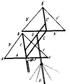
Encyclopedia of radio electronics and electrical engineering / HF antennas The idea of building this antenna was born on one of the cold autumn days, when a gusty wind mixed with snow and rain blows. It was on such a day that the fiberglass struts of the three-element "square" broke. It was clear that due to the lack of suitable material, it would not be possible to restore the antenna in the near future. This is where the dilemma arose: either make a new antenna in a short time that has the characteristics of the popular "double square", but does not contain insulating materials, or be left without an antenna until spring. Of all the antennas, the antenna with vibrators in the form of the Greek letter D, the well-known "Delta loop", seemed to be the most suitable in terms of simplicity of design and a minimum of necessary materials. This all-metal delta antenna was designed, manufactured and configured in just three days. The design of a single-band version of the antenna is shown in fig. 1. Thin-walled duralumin pipes A, A', C and C40 (their diameter is 1 mm) are attached to the ends of the bearing traverse E (duralumin pipe with a diameter of 30 mm), the ends of which are connected by aluminum or copper wires B, B', F and F' with a diameter 1,5...2,5 mm. Auxiliary traverse D prevents tipping of the antenna and, like the main traverse E, is attached to the vertical mast G. In addition, traverse D additionally strengthens pipes C and C'.
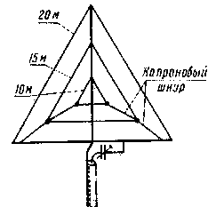
Pipe A with wires B and F forms the active element of the antenna. When it is fed in the center of pipe A, the antenna will have a horizontal polarization, so the vertical pipe C will not affect the characteristics of the antenna and it can not be isolated from the wires B and F at point c. The above fully applies to the passive element. If, however, there is no firm confidence in the symmetry of the currents in the elements of the antenna, then insulators should be placed at points b and b'. The antenna can also be made as a triband. In this case, the elements of higher frequency ranges are made of a wire with a diameter of 1,5 ... 2 mm and stretched using a nylon cord inside the elements for a range of 20 m (Fig. 2).
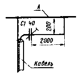
The optimal length of the traverse for a tri-band antenna is 2100 mm, which is approximately 0,1 L, for a 20-meter, 0,15L, for a 15-meter and 0,2L, for a 10-meter band, while the passive element on the 20-meter band it is advantageous to use it as a director, and on the rest - as reflectors. Then the gains and forward/backward radiation ratios are approximately the same for all three bands, although in this case the maximum radiation pattern on the 20 m band will be rotated by 180° with respect to the 15 and 10 m bands. Antenna dimensions for 20. 15 and 10 m bands are given in the table. It should be borne in mind that the ratios between the dimensions of pipe A (A1) and wires B(B') and F(F1) can be changed within fairly wide limits while maintaining the element perimeter unchanged. In this case, the dimensions of the pipe B (B') will also naturally change. However, the selected shape of the element - an equilateral triangle - is close to optimal and should provide the maximum gain. The 20 m range frame is powered by a coaxial cable with a wave impedance of 75 ohms through a G-matching device (Fig. 3). The maximum capacitance of the capacitor C1 is 40 pF, the diameter of the matching device tube is 10 mm.
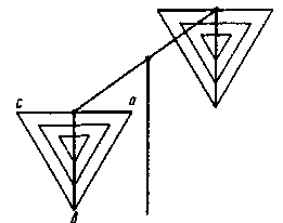
The active elements of the 15 and 10 m bands are fed through separate coaxial cables with a wave impedance of 75 ohms through balancing transformers on ferrite rings. Transformation ratio 1:1. It is convenient to tune the antenna in an inverted position (Fig. 4). This position can also be used, which, however, reduces the height of the antenna. In addition, there is a deflection of pipes A and A', and also there is a problem of installing braces for fastening the vertical mast G, which can "cling" to the elements.
First, the antenna elements are adjusted using a heterodyne resonance indicator, connecting it with one or another element near the point in (b'). The length of the wire parts of the elements is initially taken with a small margin compared to that indicated in the table. It is reduced during tuning by twisting the wires B (B ') and F (F ') between each other at point b and at the same time moving the twist point along pipe C upwards so that the wires sag slightly (due to the deflection of pipes A and A '). At this stage of the setup, the feeders should be disabled. After setting the resonant frequencies (-5% of the average frequency for the director and + 5% for the reflector) of all antenna elements, feeders are connected and, by changing the length of the passive elements within a small range, tune the antenna to maximum back lobe suppression. As a signal source, a quartz oscillator with a horizontally polarized antenna is used, at a distance of at least 80 ... 100 m. This procedure is repeated several times to take into account the mutual influence of the elements when their length changes.
Next, remove the antenna pattern, and if it is satisfactory, return the antenna to its working position (angle up). Using a SWR meter, the standing wave ratio in the feeders is determined in all ranges, and the G-matching device is adjusted. In the described antenna, the SWR within the 20-meter range after tuning did not exceed 1,2, and on the remaining ranges it was about 1,5. The remaining parameters were similar to those of the "double square" antenna. A few words about the possible modification of the antenna. It has been observed that antenna parameters such as SWR and the forward/backward radiation ratio change much less within the 20-meter range if the effective diameter of the wires B (B') is brought closer to F (F') to the diameter of the pipe A (A') . To do this, the wire part of the elements can be made of two parallel wires spaced apart by a distance of 25 ... 30 mm. Author: S. Bunin (UB5UN), Kiev; Publication: N. Bolshakov, rf.atnn.ru
Machine for thinning flowers in gardens
02.05.2024 Advanced Infrared Microscope
02.05.2024 Air trap for insects
01.05.2024
▪ Transparent and silent robotic eel developed ▪ Women win chess more than men
▪ section of the site Amateur Radio Technologies. Selection of articles ▪ article Seven Fridays in a week. Popular expression ▪ article Which peoples practiced artificial deformation of the skull and why? Detailed answer ▪ article Working with methanol. Standard instruction on labor protection ▪ article Electronic ignition for a car. Encyclopedia of radio electronics and electrical engineering ▪ article Electric stove. Encyclopedia of radio electronics and electrical engineering
Home page | Library | Articles | Website map | Site Reviews
www.diagram.com.ua |

 Leave your comment on this article: