
|
|
ENCYCLOPEDIA OF RADIO ELECTRONICS AND ELECTRICAL ENGINEERING Range vibrators. Encyclopedia of radio electronics and electrical engineering
Encyclopedia of radio electronics and electrical engineering / HF antennas The antenna, the design of which is clear from the figure, works quite satisfactorily on all 12 television channels. It can be made both from copper wire with a diameter of 5 mm, and from copper tubes with a diameter of 10 to 20 mm. It does not require matching and balancing devices.
From the editorial board. We asked an antenna specialist, well-known to our readers, candidate of technical sciences K.P. Kharchenko to express his opinion about Comrade Gasparyan's antenna. In the article published below, K.P. Kharchenko describes various types of antennas operating in a wide range of waves. In particular, he points out that the antenna proposed by comrade Gasparyan is a kind of inhomogeneous symmetrical vibrator of a planar type, and gives its correct design (in his note, comrade Gasparyan made inaccuracies, speaking about the dimensions of the antenna, the range of working will, and erroneously pointed out that it does not require balancing and matching). The problem of creating a band antenna of a relatively simple design arose long ago. Partially, she received her practical permission already in 1937, thanks to the efforts of S. I. Nadenenko. The design of a symmetrical range vibrator proposed by him, schematically shown in fig. 1 has stood the test of time and is still widely used today.
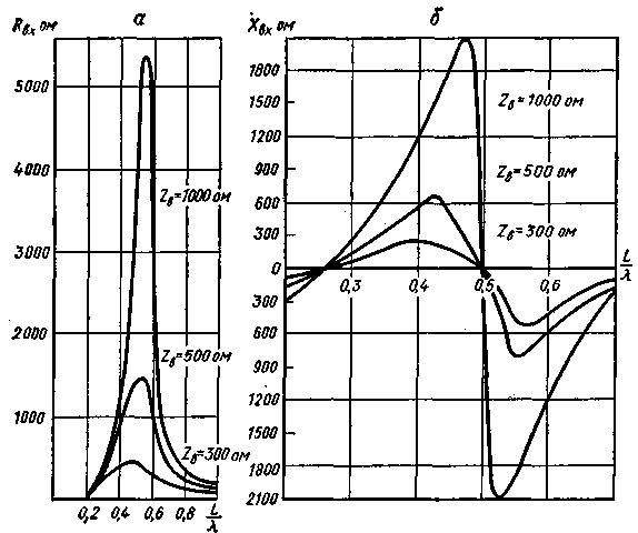
When studying the directivity characteristics of a symmetrical vibrator, it was found that with the lengths of the vibrator arms ranging from zero to 0,65 l, (where l is the wavelength), the direction of the main radiation is perpendicular to the axis of the vibrator. Consequently, the requirement for the invariance of the direction of the main radiation, imposed on band antennas, is fulfilled for a symmetrical vibrator in a very wide range of waves. The input impedance of a symmetrical vibrator depends on the ratio L/l and on the magnitude of the wave impedance of the vibrator Zв. The last dependence separately for active (Rin) and reactive (Хin) components is shown in fig. 2a and 2b. It can be seen from them that with a decrease in Zv, the oscillations of Rin and Xin become smaller. Reducing the wave resistance is achieved by increasing the diameter D of the vibrator.
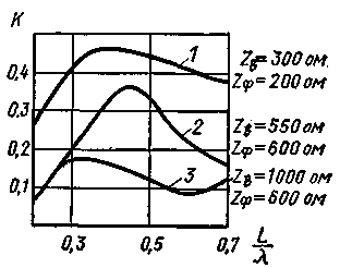
To reduce wind loads and the weight of the vibrator, its arms are made of separate wires located along the generatrices of the cylinder. With six to eight wires, the wave resistance of such a vibrator approaches the wave resistance of a vibrator whose arms are made of a cylinder with a solid surface. For better matching in the range of waves of the input impedance of the antenna with the characteristic impedance of the feeder, the latter must be correctly selected. The operating mode of the feeder is entirely determined by the value of the traveling wave coefficient K, which depends on the ratio between Zv and Zf, where Zf is the wave impedance of the feeder. Figure 3 shows curves showing how K will change depending on various L / l, Zv and Zph. If at Zv=300 ohm and Zph=200 ohm (curve 1) in the entire wave range the feeder mode can be considered satisfactory, then at Zv=1000 ohm and Zph=600 ohm (curve 3) the feeder will operate with a very low efficiency. d. Thus, for the normal operation of the feeder, it is necessary that both at the beginning of the range, when Rin is small (see Fig. 2), and in the middle of it, when Rin is maximum, the value of Zf differs slightly both up and down from the value Rin.
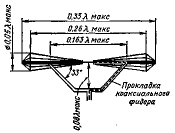
When calculating symmetrical range vibrators for operation on short waves, the limits and values of the parameters of the vibrator and feeder are selected according to the following formulas: 4L>l>1,56p; D=0,03lmax; Zf=200 ohm. At waves longer than 4L, the antenna-to-feeder matching condition is violated, and at waves shorter than 1,56L, the radiation pattern in the main direction bifurcates. The so-called shunt vibrators developed by G. 3. Eisenberg are also used as band antennas. The shunt vibrator is schematically shown in fig. 4. The active component of the input resistance of such a vibrator with the dimensions shown in fig. 4, change
in the operating frequency range from 90 to 340 ohms. If we replace the shunt vibrator with an equivalent two-wire line, then it will have the circuit shown in Fig. 5. As can be seen from it, the equivalent circuit includes a line 1-5-2-6 open at the end, consisting of two parts 1-3 - 2-4 and 3-5-4-6 with unequal wave impedances, and shunt 3 - 7-4. There is a significant distributed electromagnetic coupling between the shunt and the 1-3-2-4 line section, which is not reflected in the equivalent circuit.
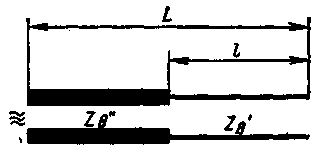
The presence of two branches in the vibrator (open and closed) creates favorable conditions for the input resistance to change as little as possible. This allows, by selecting the dimensions of the vibrator, to achieve a good matching of its input impedance and the wave impedance of the feeder in a wide frequency range. The presence of a shunt leads to the transformation of the input resistance in the direction of its increase. This circumstance can be considered an advantage when there is a need to collect in-phase gratings from shunt vibrators and use high-resistance symmetrical feeders. When the antenna is powered by a coaxial feeder with a relatively lower wave impedance, on the contrary, it is a disadvantage. Based on the study of the properties of an inhomogeneous long line with losses, the author of these lines showed the possibility of constructing a range vibrator with relatively lower windage and weight than those described earlier. The general view of such a vibrator is given in Fig. 6, and its equivalent circuit, made in the form of an inhomogeneous two-wire line, is in fig. 7. Here, a section of an inhomogeneous line with Z "b can be considered as a kind of transformer with losses (these are useful losses due to energy radiation), which converts Rin and Xin in the direction of improving matching with low-resistance feeders.
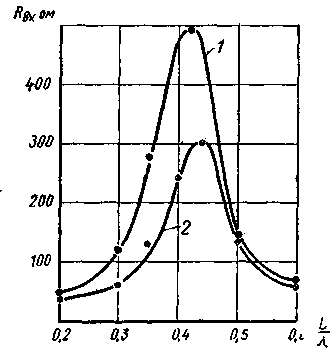
This is illustrated in Fig. 8, curve 1 of which shows the dependence of Rin on L/l for a homogeneous vibrator (the diameter of the arm is the same along its entire length), and curve 2 shows a non-uniform vibrator (the diameter of the arm along its length is not the same). In this case, the values of the parameters (see Fig.1 and Fig.6) and L for both vibrators were taken the same, and for a non-uniform vibrator, in addition, l/L=0,47; D/d=9.
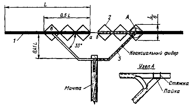
Curves fig. 8 show that the equivalent wave impedance of a non-uniform antenna is 1,3-1,4 times less than that of a homogeneous one (for the given ratios). At the same time, in the manufacture of a non-uniform antenna, its weight and windage are reduced by about half compared to the above-described vibrators of both volumetric and planar types due to a significant reduction in the transverse dimensions of their end sections. A slightly modified version of a non-uniform symmetrical vibrator of a planar type, proposed by a radio amateur from Batumi, A. Gasparyan, is shown in fig. 9.
The vibrator consists of two tubes 1 with length L=0,22-0,24lmako where lmax is the maximum wavelength of the operating range. The diameter of the tubes is chosen so that the vibrator is mechanically strong. A wire or tubular structure 2 is mounted on them, which must have a galvanic contact between its elements and tubes. This structure acts as a matching transformer. For laying the feeder and mechanically fixing the vibrator on the mast, shunt 1 is used (made of the same tubes), which also has 3 galvanic contact with the tubes at points c, d. The cable (feeder) can be laid either through the shunt tubes from above (tied to them) or inside them, as shown in Fig. 1 dotted line At point b, the cable braid is soldered to tube 9, and at point a, its central conductor. To install the vibrator, a mast made of any material can be used. Literature
Author: Cand. tech. Sciences K. Kharchenko; Publication: N. Bolshakov, rf.atnn.ru
Machine for thinning flowers in gardens
02.05.2024 Advanced Infrared Microscope
02.05.2024 Air trap for insects
01.05.2024
▪ 10 trillion frames per second camera ▪ Synthesized a new type of antibiotic to fight superbugs ▪ The Earth and the Moon are formed from similar materials ▪ X-ray for communication in space
▪ section of the site Audio and video surveillance. Selection of articles ▪ Article Fragrant Prairie Flower. Popular expression ▪ article In which animals is necrophilia a common reproductive strategy? Detailed answer ▪ article Welded tires - bicycle. Travel Tips ▪ article Capacitive sensor. Encyclopedia of radio electronics and electrical engineering
Home page | Library | Articles | Website map | Site Reviews www.diagram.com.ua |


 Arabic
 Bengali
 Chinese
 English
 French
 German
 Hebrew
 Hindi
Hindi Italian
 Japanese
 Korean
 Malay
Malay Polish
 Portuguese
 Spanish
 Turkish
 Ukrainian
 Vietnamese




 Leave your comment on this article: