|
|
ENCYCLOPEDIA OF RADIO ELECTRONICS AND ELECTRICAL ENGINEERING Calculation of a vertical quarter-wave antenna. Encyclopedia of radio electronics and electrical engineering
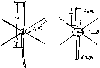
Encyclopedia of radio electronics and electrical engineering / HF antennas One of the main ways to reduce interference to television reception from amateur transmitters is the use of transmitting antennas with vertical polarization. The most common among shortwaves is a quarter-wave vertical antenna ("Ground plane"). This antenna consists of a vertical rod, the length of which is usually somewhat less than a quarter of the operating wavelength emitted by the transmitter, and a counterweight. It is made of several horizontal quarter-wave beams connected to the sheath of a coaxial cable, through which high-frequency energy is supplied from the transmitter. The radiation resistance of such a quarter-wave antenna is 28-32 ohms (depending on the outer diameter of the metal tubes from which it is built). Therefore, connecting the antenna to a 50-ohm or 75-ohm coaxial cable will introduce standing waves into the cable and waste energy. To match the vertical pin with the cable, it is necessary to use additional elements - inductors, capacitors or cable sections with certain parameters. A simplified calculation method for a "Ground plane" antenna with a horizontal counterweight and a matching cable section is described below. Antennas built according to this calculation work well on one amateur band (for example, 14 MHz) and, at the same time, radiate quite satisfactorily on two adjacent bands (21 and 7 MHz). We will give the calculation on a numerical example for the 14 MHz band. The connection of the pin with the cable supplying it and the matching cable section and the designations of their sizes are shown in fig. one.
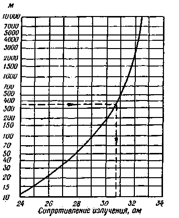
For the calculation, it is necessary to know the diameter of the metal tubes or wires from which the antenna pin and counterweight beams will be made. Let's say that we are going to use a tube with an outer diameter of 30 mm for the manufacture of an antenna, and we will make the counterweight from a wire with a diameter of 2 mm. We determine the coefficient M, which characterizes the ratio of the length of the half-wave dipole remote from the ground to the diameter of the antenna. We apply the formula: M=150000/(f(MHz)D(Mm)) Here: f is the middle frequency of the range, D is the diameter of the tubes. With f=14,2 MHz and D=30 mm we get: M=150000/(14,2*30)=352 Using the coefficient M, we determine, using the graph (Fig. 2), the radiation resistance of a quarter-wave antenna R rad (for the resonant frequency): R rad \u30,8d XNUMX ohm.
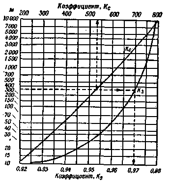
Now it is necessary to calculate the true radiation resistance Ry of the shortened antenna, which we will build; due to the influence of the earth and the counterweight, it differs from Rizl and is equal to: Ry=Rizl-Z/4Rizl Here Z is the wave impedance of the coaxial cable from which the feeder is made. In our example, let's take it equal to 75 ohms. Then: Ry=30,8-75/4*30,8=30,2 Ом. To calculate the length of the vertical pin L, you need according to the graph in Fig. 3 to determine two more auxiliary coefficients: Kc, which characterizes the change in the resistance of the antenna with a change in its length, and Kz, which takes into account the influence of the counterweight and the earth's surface. We get: Kc=535, Kz=0,97.
The graph for determining the K coefficient can only be used if the antenna length changes by no more than 10%. If the antenna is longer than the resonant one, then its impedance is inductive in nature, if shorter, it is capacitive. The length of the pin (in mm) is determined by the formula:
We have;
To determine the length of the beams of the counterweight Lnp, made of a wire with a diameter of 2 mm, we calculate M: M=150000/14,2*2=5280 and according to the graph in fig. 3 we find Ky=0,978. Then
A shortened antenna has, in addition to active, also a capacitive reactance. To compensate for it, a cable segment shorted at the end is connected parallel to the antenna; its length is chosen such that its reactance has the inductive nature of the required value. We define this inductive reactance: Xc=Z/S=75/1,22=61,5 ohm Using a slide rule or a table of tangents, we find the angle a, the tangent of which is numerically equal to the ratio of the obtained value Xc to the wave impedance Zc of the cable from which the matching segment will be made. At Zc=75 ohm: Xc/Z=61,5/75=0,82 and a=39,4° The length of the shortened segment is: Lc=(833ab)/f, mm In this formula, b is a coefficient characterizing the speed of energy propagation along the cable. For common cables with solid filling (RK-1, RK-3) b=0,67. Consequently, the Lc=(833*38,4*0,67)/114,2=154,9 мм The calculation described above takes into account that the beams of the counterweight are located horizontally; however, even with their inclined arrangement (at an angle of 30-40 ° to the ground), the mismatch is insignificant. The standing wave ratio (SWR) in the feeder can be measured by assembling a simple bridge-type SWR indicator, the circuit of which is shown in fig. 4. Here the resistances R1, R2, R3 and the radiation resistance of the antenna form a bridge. One of its diagonals is supplied with high-frequency energy from the transmitter (Per connector). Diode D1 of type D2E is included in the second diagonal.
Resistance R4 serves to reduce the output resistance of the energy source (transmitter). The inductor (Dr1) closes the circuit of the direct component of the rectified current; it is necessary if the antenna circuit does not have galvanic conductivity. When the balance of the bridge, the arrow of the device does not deviate. The mismatch of the antenna and cable causes the appearance of standing will, which is indicated by the deviation of the arrow. The procedure for measuring SWR is as follows: 1. Tune the transmitter with antenna at full radiated power. 2. Reduce the power to zero by blocking, for example, one of the pre-stage lamps with a negative bias, and disconnect the antenna. 3. Connect the transmitter input and the Per connector with a piece of cable. on the SW index. 4. Gradually, very smoothly, so as not to burn out the resistance R4, increase the power of the energy supplied to the SWR indicator until the instrument arrow deviates to the end of the scale. 5. To check the balance of the bridge, temporarily attach a resistance of 75 ohms to the Ant connector; the needle of the milliammeter should then go to zero. 6. By connecting to the Ant. the coaxial cable feeding the antenna, mark the current on the scale and determine the SWR from the curve shown in fig. 5.
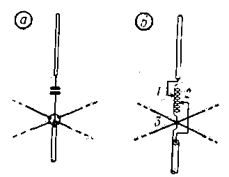
If the antenna feeder does not introduce significant losses, for example, it is made of a RK-1 or RK-3 cable and has a length of no more than 15-20 m, then an SWR of 2 and even 2,5 is quite acceptable. The total losses (the sum of losses in the feeder and losses due to mismatch) in this case will not exceed 0,5 dB. Such a decrease in power at the receiving station will not be noted by ear. A noticeable drop in the reception volume (by 1-2 points) can be observed only at an SWR of the order of 5-8. In the event that the constructed antenna has excessive SWR or its dimensions are chosen larger or smaller than it should be, it is necessary, using the SWR indicator, to adjust the antenna empirically. An antenna longer than necessary can be electrically shortened by a capacitor connected in series with the vertical part (Fig. 6a). An antenna that is too short can be electrically extended by adding an inductance to it (Fig. 6b). In this case, the antenna is tuned alternately, selecting the position of both pinches on the coil. Here, the part of the coil between pinches 1 and 2 is used to extend the vertical part of the antenna, and the lower part (2-3) replaces the matching shorted cable (Fig. 1).
In conclusion, we note that charges of static electricity accumulate on the antenna of the described type, especially during a close thunderstorm. Therefore, it is recommended to use antennas with shorted cable sections (Fig. 1) or inductance shunting the cable (Fig. 6 b) and reliably ground the cable sheath. Author: Y. Prozorovsky (UA3AW); Publication: N. Bolshakov, rf.atnn.ru
Machine for thinning flowers in gardens
02.05.2024 Advanced Infrared Microscope
02.05.2024 Air trap for insects
01.05.2024
▪ Smart speaker Huawei Sound SE ▪ Walking as a cure for depression
▪ section of the site Electrical safety, fire safety. Article selection ▪ article Make us beautiful. Popular expression ▪ article Instructor of the training center. Job description ▪ article 1260 MHz Converter. Encyclopedia of radio electronics and electrical engineering ▪ article Wonderful handkerchiefs. Focus Secret
Home page | Library | Articles | Website map | Site Reviews www.diagram.com.ua |


 Arabic
 Bengali
 Chinese
 English
 French
 German
 Hebrew
 Hindi
Hindi Italian
 Japanese
 Korean
 Malay
Malay Polish
 Portuguese
 Spanish
 Turkish
 Ukrainian
 Vietnamese


 Leave your comment on this article: