|
|


 Arabic
 Bengali
 Chinese
 English
 French
 German
 Hebrew
 Hindi
Hindi Italian
 Japanese
 Korean
 Malay
Malay Polish
 Portuguese
 Spanish
 Turkish
 Ukrainian
 Vietnamese
|
ENCYCLOPEDIA OF RADIO ELECTRONICS AND ELECTRICAL ENGINEERING Methods for balancing antennas. Encyclopedia of radio electronics and electrical engineering
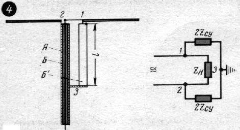
Encyclopedia of radio electronics and electrical engineering / Antennas. Measurements, setup and matching Many HF and VHF antennas, in particular television ones, belong to the class of symmetrical antennas. When such antennas are fed through a coaxial feeder, their operation largely depends on the performance of transitional baluns. However, often radio amateurs, when making an antenna, do not make such devices at all or design them incorrectly, based on erroneous recommendations that are found in some popular books on antenna devices. This article describes methods for balancing antennas and the properties of some balancing devices, as well as recommendations for their implementation. Direct connection of a coaxial feeder to a symmetrical antenna (for example, to a dipole) breaks the symmetry of the currents in it and leads to the appearance of a current on the outer surface of the feeder screen, that is, it causes the appearance of an antenna-feeder effect. On fig. 1a shows such a connection of a dipole with a feeder. In this case, the output voltage of the feeder is applied not only to the input terminals 1-2 of the symmetrical vibrator, but also to one terminal 2 and the shielding shell 3 of the feeder.
The voltage between the terminals of the vibrator causes symmetrical currents in it, closing from one half of the vibrator to the other, as shown in fig. 1, but with solid arrows. The voltage between the right half of the vibrator and the cable sheath induces an additional current, shown by dashed arrows. The appearance of this current leads to the emission (reception) of electromagnetic energy by the feeder, which breaks the symmetry of the currents in the antenna and, as a result, distorts the radiation patterns. On fig. 1, b shows the equivalent circuit of a symmetrical antenna with a directly connected coaxial feeder, where the antenna is shown as a load resistance Rn of the output terminals of the generator or consumer (transmitter or receiver). As can be seen from the diagram, one of these terminals will be connected not only to the load resistance Rn, but also to the ground through the capacitor C, the plates of which are the antenna vibrator and the shielding of the feeder. Thus, the symmetry of the antenna is broken. Therefore, to connect a coaxial feeder with a symmetrical antenna, special adapter devices are used, also called baluns, due to which the electrical symmetry of each half of the antenna relative to the shielding of the feeder is achieved. Transition device type "locking cup" shown in fig. 2a.
In this device, the input terminals 1-2 of the antenna vibrator are directly connected to the inner and outer conductors of the coaxial cable, which is placed inside the metal cup B along its axis so that the walls of the cup and the shielding sheath B of the cable form a coaxial line with a characteristic impedance r (formulas for calculating wave impedances of coaxial and two-wire lines are given in the journal "Radio" N 11 for 1962). The input impedance of this line between points 2 and 3 is:
When l=l/4, the value of Z2,3 is large, the current from point 2 to point 3 will not flow, and the currents on both sides of the antenna will be equal. If the length l of the glass B is different from l / 4, then Z2,3 will not be large and, as can be seen from the equivalent circuit in Fig. 2b, the symmetry is broken: at point 2, part of the current will branch off to the ground and the voltages between the ground and points 1-2 will no longer be equal and out of phase. Therefore, the operating frequency band of such a balancing device is small. Usually it does not exceed 10% of the value of the fundamental frequency for which the device is designed.
The frequency band of a balancing device with a glass can be increased by introduction of the second segment of the coaxial line with the same wave resistance as the glass (Fig. 3a). In this case, as can be seen from the equivalent circuit (Fig. 3,b), the resistances of points 1 and 2 relative to the ground will be equal, regardless of their value, that is, Z1,2=Z2,3. Due to this, the antenna power will be symmetrical over a wide frequency band. The difference between the devices shown in Fig. 3 and Fig. 4 lies in the fact that in the latter two elements (B and B') are placed side by side, forming a two-wire line closed at the end. The input impedance of this balun is
where r' is the wave impedance of the two-wire line. Balancing device fig.4 simple in design, operates in a wide frequency band and is most often used in amateur practice. One of the conductors of this balancing device is the shielding shell of the coaxial feeder (element B), as the second (element B') either a piece of cable from which the feeder is made, or a tube of equal diameter can be taken. The main advantage of this device over the previous one (Fig. 3) is half the length.
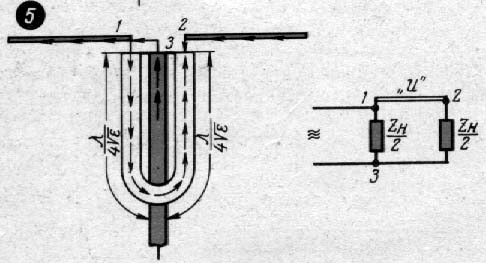
Scheme of balancing device type "U-elbow" shown in Fig.5, a. Here the central wire of the main coaxial feeder is connected to terminal 1 of the left half of the vibrator. From the same point, voltage is supplied to terminal 2 of the right half of the vibrator through a piece of cable with a length of l/2, where l is the wavelength in the cable (taking into account shortening). The phase of the voltage during the passage of a section of cable with a length of l / 2 shifts by 180 °, therefore, the required anti-phase voltage is supplied to the vibrator terminals. The shielding sheaths of the cables are interconnected.
Author: Ing. K. Kharchenko; Publication: N. Bolshakov, rf.atnn.ru
The existence of an entropy rule for quantum entanglement has been proven
09.05.2024 Mini air conditioner Sony Reon Pocket 5
09.05.2024 Energy from space for Starship
08.05.2024
▪ 512 GB SSD from Samsung in BGA chip format ▪ Huawei NetEngine 9000 Petabit Backbone Router ▪ Miniature board Tah for controlling electronic devices via Bluetooth
▪ site section Preamplifiers. Article selection ▪ article Eat to live, not live to eat. Popular expression ▪ article Why do clouds have different shapes? Detailed answer ▪ article Semiconductor solar panels. Encyclopedia of radio electronics and electrical engineering
Home page | Library | Articles | Website map | Site Reviews
www.diagram.com.ua |


 Leave your comment on this article: