|
|


 Arabic
 Bengali
 Chinese
 English
 French
 German
 Hebrew
 Hindi
Hindi Italian
 Japanese
 Korean
 Malay
Malay Polish
 Portuguese
 Spanish
 Turkish
 Ukrainian
 Vietnamese
|
ENCYCLOPEDIA OF RADIO ELECTRONICS AND ELECTRICAL ENGINEERING The amplifier has earned, what's next? Improvement methods. Encyclopedia of radio electronics and electrical engineering
Encyclopedia of radio electronics and electrical engineering / Tube Power Amplifiers But now, finally, behind the week (or maybe months) of painstaking work. And the long-awaited day has come. The amplifier worked, and, moreover, exactly as it was supposed to work - excellent. Very soon you will see that with the most captious attitude to the amplifier, no claims can be made: all the parameters for which it is designed are fully implemented. But does this mean that the limit of the possible has really been reached and that nothing can be changed for the better? Far from it. In the matter of improving any radio device, there can be no limits, especially for real radio amateurs - inquisitive and creative people. And here we can outline several directions. The first lies in the further improvement of the amplifier itself. It should be noted that it is unlikely that it will be possible to improve the performance of the amplifier that you made according to the descriptions given: if you carefully and conscientiously did everything that was recommended for the manufacture of transformers, selection of parts, and especially adjustment and measurements, it means that from the amplifier "squeezed out" everything to the last drop. Amplifier upgrades are not only possible. But it is also quite justified, especially if you chose one of the simplified options to begin with, for example, did not introduce a clang register into the design, or limited yourself to two tone controls instead of four. Now is the time to introduce these "excesses" into your amplifier. It is perfectly acceptable to replace the final tubes with more powerful ones if you finally manage to get them or if the output power of your amplifier seems insufficient. Or maybe, at first, for the test, you limited yourself to making a single-channel version, so the transition to stereophony is another task. Another way is to abandon the single-channel amplification and sound reproduction scheme and switch to a multi-channel one (for a start, a two-channel one). We have already said that with a bandwidth of the entire path from 20 Hz to 20 kHz, the "range overlap" is 1:1000. It's very big, just huge. Recall for comparison that in any all-wave radio receiver, the entire broadcasting range (it ranges from 150 kHz on long waves to 100 MHz on VHF) is smaller in overlap, only 1:666. And yet this range is divided into at least four separate bands: LW, MW, KB and VHF. It should be taken into account that a significant part of this range (from 20 to 64 MHz) is not used for broadcasting at all. Such a breakdown into subbands is due to the fact that the operating conditions of the receiving part of the circuit at different frequencies are too different. In a low-frequency amplifier, the same laws apply, but there is a specific amplification at different frequencies. It is enough to point out one fact: the inductive resistance of the primary winding of the output transformer with inductance L = 40 H at a frequency of 20 Hz is 5 kOhm, and at the other end of the operating range (frequency 20 kHz) - already 5 MΩ! The difference, mind you, is 100000%! And we want this transformer to work equally at all frequencies. The same applies to the influence of various parasitic (more precisely, inevitable) mounting capacitances, stray fields of transformers, and interelectrode capacitances of lamps. If in the lower part of the operating range (from 1000 Hz and below) their influence is almost imperceptible, then at frequencies above 10 kHz they become full and undivided "masters" of the circuit, creating unpredictable positive and negative feedbacks that can completely disrupt the normal operation of the amplifier and even turn it into a generator. And here only one solution is visible: to divide the entire low-frequency spectrum into at least two and entrust the processing of each part of the spectrum to separate amplifiers. We are talking about this, assuming that a radio amateur, who has assembled one of the amplifiers described here, will later be able to use it as a low-frequency one, and to work with the upper part of the spectrum, build an additional, high-frequency channel loaded on his additional remote loudspeakers. But the most fascinating and unknown awaits inquisitive and inquisitive radio amateurs on the third path - the path to which this chapter is mainly devoted. This is due to the fact that the ultrasonic frequency converter and the speaker system for which it works are not two separate devices, but one single system, the links of which are inextricably linked, like two adjacent stages in an amplifier circuit. Any ultrasonic frequency converter produces a signal at the output with predetermined parameters, which, in the ideal case, the connected speaker system does not affect at all, and in the worst case, reduces the efficiency of the amplifier and increases non-linear distortion with non-optimal matching. In turn, no amplifier can affect the frequency band reproduced by the acoustic system, its unevenness and non-linear distortions created by the emitters. If we imagine the complex amplifier + acoustic system as a single system, then it will be possible to implement their mutual influence, covering the entire system with a chain of negative and positive feedbacks with certain specified parameters. What is the "highlight" of this idea? To answer this question, we have to return to the theory again. It is known that any loudspeaker is an electromechanical system, the electrical part of which is determined by the inductance of the voice coil, its active resistance and the parameters of the magnetic field, in the gap of which the coil moves. The mechanical part of the system is characterized by the mass of the diffuser, the rigidity of its suspension, the inertia of the entire moving system, and the diffuser radiation area. An additional and very significant influence on the mechanical characteristics of the acoustic system is exerted by the shape and dimensions of the case, which is a screen that prevents or reduces the degree of "acoustic short circuit" between the front and rear sides of the radiator cone. Some of these parameters are invariable and are incorporated in the design of the emitter (for example, the active resistance of the coil, the mechanical mass of the diffuser, the rigidity of its suspension, etc.). Others may change continuously during the operation of the loudspeaker (for example, the inductance of the coil, its reactance). In addition, the entire system has multiple intrinsic electrical and mechanical resonances, which manifest themselves to varying degrees at different frequencies, which can be inherent both in this type of radiators and in a particular instance. These factors make the frequency response of radiation in terms of sound pressure largely unpredictable and uneven. In addition, we should not forget that the loudspeaker is a non-linear system in which the shape of the audio frequency current flowing through the coil differs significantly from the shape of the voltage applied to it. But it is on the form and value of this current that the mechanical oscillations of the diffuser depend. Therefore, no matter how hard we try to linearize the shape of the voltage applied to the loudspeaker, the shape of the current in the coil is beyond our control. It is a completely different matter if we have a voltage whose shape exactly repeats the shape of the current in the coil. Then this voltage in the form of negative feedback could be introduced into the amplifier circuit and thus affect the process of mechanical oscillations of the diffuser, eliminating surges and dips in the frequency response of the radiation. Fortunately, such a possibility exists. To implement it, it is enough to connect in series with the loudspeaker from the side of its grounded end an active non-inductive (non-wire) resistance, which is 3 ... 5% of the total resistance of the voice coil. For a four-ohm loudspeaker, this will be 0,15 ... 0,2 ohms. It is possible that finding such a resistor will not be easy. In this case, it can be replaced with a small piece of high-resistance wire made of constantan, nichrome, manganin. When the loudspeaker is operating, exactly the same current will flow through this resistor as through the voice coil, and, therefore, a voltage will drop on it, the shape of which exactly repeats the shape of the current, which is what we needed. This feedback voltage must be returned to the amplifier by a separate independent two-wire line and applied to the input of the final stage, having previously formed the desired value and polarity of the feedback signal using a special additional broadband amplifier stage. It is unacceptable to use the one that goes from the output transformer to the speakers as a neutral wire, since its active resistance with a sufficiently long connecting line (2 ... 5 m) is commensurate with the resistance of the additional resistor. This is a general description of the physics of the process. But we will not give detailed data on its circuit implementation. Let everyone who wants to experiment in this completely new direction find their own solution. In the end, the purpose of this book is not just to describe a particular amplifier for repetition, but to encourage radio amateurs to be creative, to instill a taste for serious research work, the results of which will bring immeasurably more joy than the opportunity to listen to the high-quality sound of an amplifier, even if it was created by oneself.
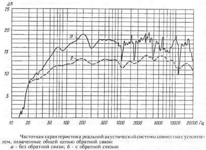
But so that the reader does not think that this direction is nothing more than a beautiful theoretical refinement, we inform you that on one of the amplifiers described in the book (no matter which one). The author used the described method for obtaining electrical feedback between a group of loudspeakers and the final stage of the UZCH, which gave excellent results. On fig. two frequency characteristics of this acoustic system in terms of sound pressure are given, obtained during tests conducted in the MTUCI electroacoustic laboratory. In the figure, the solid line shows the frequency response of the acoustic system without feedback, the dashed line - with feedback. The results do not require comments. Literature
Author: tolik777 (aka Viper); Publication: cxem.net
Machine for thinning flowers in gardens
02.05.2024 Advanced Infrared Microscope
02.05.2024 Air trap for insects
01.05.2024
▪ Sound card Creative Sound Blaster Z SE ▪ High-strength steel for buildings and armored vehicles ▪ External battery ZMI 20 Power Bank with 120W charger ▪ NASA will build a supersonic aircraft
▪ section of the site for those who like to travel - tips for tourists. Article selection ▪ article Great maneuvers. Popular expression ▪ article How much does our skeleton weigh? Detailed answer ▪ article Magnetic field meter. Children's Science Lab ▪ article FSK number determinant. Encyclopedia of radio electronics and electrical engineering
Home page | Library | Articles | Website map | Site Reviews
www.diagram.com.ua |

 Leave your comment on this article: