|
|
ENCYCLOPEDIA OF RADIO ELECTRONICS AND ELECTRICAL ENGINEERING High quality economical power amplifier. Encyclopedia of radio electronics and electrical engineering
Encyclopedia of radio electronics and electrical engineering / Transistor power amplifiers As you know, symmetrical broadband final amplifiers LF introduce minimal distortion at all levels of output power. One of the most advanced versions of a high-quality amplifier with these properties was published in [1]. A detailed description of this amplifier can also be found in [2]. The amplifier is designed on transistors of an additional structure and is symmetrical and push-pull from input to output. A double differential stage is switched on at the input, and each of the arms of the output stage is an amplifier covered by negative feedback (NFB) with a voltage transfer coefficient greater than one. The advantages of these circuit solutions are described in detail both in these works and on the pages of the Radio magazine [3, 4].
When testing several instances of the amplifier, assembled according to a similar scheme on the domestic element base, one drawback was revealed - a significant decrease in the supply voltage utilization factor (SIF) when operating on a low-resistance load *. And this entails the need to increase the supply voltage to obtain a given power, which leads to a decrease in efficiency, a deterioration in the thermal regime of the output transistors, and an increase in the dimensions of the amplifier. 50% and, along the way, reduce the output impedance of the amplifier by 35% while maintaining the rest of the characteristics. The amplifier described below is suitable for amplifying high-power audio signals in high-end sound reproduction installations, as well as for use as a high-power broadband, operational amplifier. Main technical characteristics of the amplifier Rated (sinusoidal) output power, W, with load resistance, Ohm:
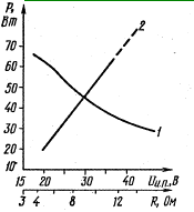
The parameters were measured when the amplifier was powered from a stabilized source of ±31,5 V. When using an unstabilized source, in order to maintain the characteristics, the supply voltage should be increased by 1 ... 3 V, depending on the capacitance of the filter capacitors. It should be noted that for the level of non-linear distortions, the upper limit value is indicated, due to the capabilities of the measuring equipment available to the authors. The time taken to establish the transient characteristic was also measured when a voltage drop with a rise time of 0,1 μs was applied to the input. For an output amplitude of 10 V, it turned out to be approximately 1 μs, and the spikes on the flat part were no more than 15'%. On fig. 1 shows the dependences of the maximum output power, corresponding to a harmonic coefficient of 0,2%, on the load resistance RH with a stabilized power supply of ±31,5 V (curve L), as well as on the supply voltage at RH 7,7 Ohm (curve 2).
current (VT7, VT8), which work in antiphase. Such an inclusion doubled the "buildup" current, reduced non-linear distortion and improved frequency properties; amplifier as a whole. Each of the arms of the symmetrical output amplifier is made according to the Darlington scheme. It is a three-stage amplifier (in two stages, the transistors are connected according to the circuit with a common emitter and in one - with a common collector). The amplifier is covered by a frequency-dependent OOS, which determines its voltage transfer coefficient, which is close to three in the audio range. Since the feedback signal taken from the resistor R39 (R40) is proportional to changes in the current of the output transistor, a rather rigid stabilization of the operating point of this transistor is additionally carried out; The bias voltage of the output stage is determined by the resistance of the collector-emitter junction of the transistor VT9 and is regulated by resistor R24. The bias voltage is thermally stabilized by the VD4 diode, which is mounted on the heat sink of one of the powerful transistors. The total OOS for direct current through the resistor R33 stabilizes the mode of all stages and brings the output potential closer to the input, which is zero. The R17C5 circuit reduces the ac FOS depth by converting the amplifier into an active filter with a gain of about 27 dB.
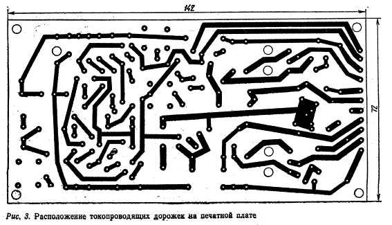
Correction elements R16, C4, C6 -C11 ensure the stability of the amplifier and equalize its frequency response. The R2C1 passive low-pass filter prevents RF signals from entering the input. Chain C12R45L1R47 compensates for the reactive component of the load resistance. On transistors VT12 and VT13, a unit for protecting output transistors from current and voltage overloads is assembled. Resistor R1 allows, if necessary, to limit the output power in accordance with the signal level from the preamplifier and the capabilities of the speaker used. The amplifier is mounted on a printed circuit board (Fig. 3) with dimensions of 142X72 mm, made of double-sided foil fiberglass 1,5 mm thick. On the side of the parts (Fig. 4), the foil is left in the form of a continuous "ground" field. Around the holes for the leads of parts within a radius of 1,5 ... 2,5 mm, the foil was removed. Outside the board there are fuses FU1-FU3, transistors VT16, VT17, which are fixed on heat sinks with an area of at least 1000 cm2, and a diode VD4. In addition, the resistor R1 can be attached to the front panel so that the maximum output power can be quickly adjusted.
In addition to those indicated in the diagram, other low-power high-frequency silicon transistors can be used in the amplifier, for example, KT342A, KT342B and KT313B, KT315 and KT361 (with indices from B to E). Transistors VT14 and VT15 (possible replacement -KT816V, KT816G and KT817V, KT817G or KT626V and KT904A) are equipped with ribbed heat sinks with dimensions of 23X X25X12 mm. KT818GM and KT819GM transistors can be used as output transistors, which allow, with an increase in the supply voltage (see Fig. 1), to obtain powers over 70 watts. Zener diode VD1 can also be D816G or 2S536A, VD2, VD3 -KS147A (with appropriate correction of the resistances of resistors R11 and R14). Resistors of the SP5-3 type were used as trimmers. Resistors R39, R40, R46, R47 are made of high-resistance wire with a diameter of 0,8 mm, resistors R35, R38, R45, R47 are MOY, the rest are MLT. The inductor L1 is wound on a resistor R47 with a PEV-2 0,8 wire in one row until the resistor case is filled. Capacitor C2 - IT or K50-6, C5 - K50-6, the rest - KM. Setting up the amplifier is as follows. First, without connecting powerful transistors, a load dummy is connected to the output of the amplifier and, gradually increasing the supply voltage, by the absence of surges in the consumed current or a significant drop in voltage across the load, they are convinced of the correct installation. After that, the output transistors are connected and the resistor R18 sets the output voltage close to zero (no more than 10 mV), and the resistor R24 sets the quiescent current at the level of 15 ... 25 mA. In conclusion, we note that the use of a relatively large number of transistors in this amplifier is compensated by its manufacturability. The circuit solutions used, the presence of local environmental protection provide high performance and good reproducibility without careful adjustment. In this case, the preliminary selection of transistors is practically not required. Due to the optimal use of the supply voltage and low quiescent current, the amplifier is economical. And the possibility of obtaining a wide range of maximum output powers at loads from 4 to 15 ohms by changing the supply voltage (in addition, it may be necessary to select resistors R21 and R25 so that the currents through them are within 10 ... 20 mA) provides versatility use of this amplifier. Publication: cxem.net
Machine for thinning flowers in gardens
02.05.2024 Advanced Infrared Microscope
02.05.2024 Air trap for insects
01.05.2024
▪ Free replacement of displays in Motorola smartphones ▪ Testosterone prevents men from thinking ▪ Ancient people could see dinosaurs ▪ The brightest galaxy in the universe discovered
▪ section of the site Aphorisms of famous people. Article selection ▪ article I just work as a magician. Popular expression ▪ article Who are the gnomes? Detailed answer ▪ article Head of Internal Control Department. Job description ▪ article There is no alternative. Encyclopedia of radio electronics and electrical engineering
Home page | Library | Articles | Website map | Site Reviews www.diagram.com.ua |


 Arabic
 Bengali
 Chinese
 English
 French
 German
 Hebrew
 Hindi
Hindi Italian
 Japanese
 Korean
 Malay
Malay Polish
 Portuguese
 Spanish
 Turkish
 Ukrainian
 Vietnamese


 Leave your comment on this article: