6H13S lamp fixed bias options. Encyclopedia of radio electronics and electrical engineering

Encyclopedia of radio electronics and electrical engineering / Tube Power Amplifiers
 Comments on the article
Cathode bias is not suitable for this lamp (and even in transformerless amplifier circuits it is generally impossible). Therefore, a fixed external offset from a separate source. What?
Further analysis is given for two output stage OTL modes (1) Ua=100V, Ug=-33V, Ia=100mA (2) Ua=160V, Ug=-70V, Ia=65mA. Here and below, the numbers are given for one triode. In both cases, the anode power at idle is 10W at the nominal mains voltage (and, therefore, at the anode). But this is the denomination. But in practice, the mains voltage walks, and the anode voltage will float along with it. This is where the scheme can go wrong. Further, we assume network fluctuations within 175-260V. These are really extreme conditions, but what the hell is not joking ...
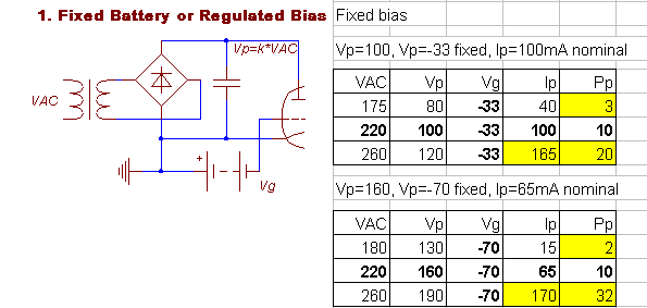
1. Rigidly fixed battery or stabilized bias. Absolutely unacceptable! With an increase in the mains and anode voltages, the anode current goes up according to the 3/2 law and the lamp dies. Soon enough if the power margin is small. In my case, when plugged into an electric kettle, the mains voltage drops by 6V, and the anode current drops by 20% (from 48 to 40mA) - what will happen if the mains voltage rises by 20V ?!

2. Fixed ratio Ua/Uc. This will be the case if the sources are fed from the same network, and their (anodic primarily) output resistance is small enough. An increase in the anode voltage is partially offset by an increase in a decrease in the grid potential. With mu=2, if Ua=2Ug, the current will be constant, and the power will be proportional to the mains voltage. In the selected modes, however, full compensation does not occur. It is easier to represent this graphically by replacing the marking of the Ua axis with the mains voltage on the I–V curve:

The most attractive bias is in the constant power mode, where the overcompensation of the anode shift by the grid CURRENT software leads to an almost unchanged anode power.

A linear approximation for any mode of this lamp is Uc = -0.75*Ua + dU, dU=+37..+60V (excluding the output resistance of the anode source and the output resistance of the common wiring). It is clear from the equation how to obtain such a bias: we take a source that gives an output of -0.75 from the anode one, and remove the excess of 37..60V with a zener diode. In practice, it is more convenient to put the zener diode at a voltage of about 10V, less than the required shift, and adjust the actual shift with a potentiometer.
Option 1 (for Ua=100V) (without adjusting potentiometer).

The CSS soft start capacitance at start locks the lamp for 2-3 seconds. When the power is turned off, the 27V zener diode fixes -27V on the grid for about 10 seconds.
Option 2 (for Ua=160V, implemented in hardware in the Mammoth I project).

For the convenience of adjustment (yes, simply because the secondary winding was only at 72V, and it was recruited from two incandescent and two "anode") - the zener diode was taken at 24V, and the adjustment in the left shoulder is carried out by potentiometers R4 (common) and R5 (balance) . Unlike the previous scheme, here the compensation actually occurs not in terms of power, but rather in terms of current. Because the power ceiling was not enough to embed a 50V zener diode. The resistance of the voltmeter is about 100 kOhm (not fundamental, the main thing is not to be too small).
And now I warn you ... If the time constant of the grid power filter is significantly greater than that of the anode one (and it cannot be otherwise) - the compensation is slow, and immediately after the change in the mains voltage, the lamp behaves as in battery bias. That is, it goes to pieces. You still need to have a margin for anode power and current. And if there is time, select the minimum acceptable capacitances in the bias filter in order to speed up its response. Somehow, out of habit, I did not regret the farad ...
Acknowledgments, links, notes
- Website of Atma-Sphere and its founder Ralph Carsten, atma-sphere.com
- Site of Atma-Sphere amplifier owners, otlamp.com
Publication: klausmobile.narod.ru
 See other articles Section Tube Power Amplifiers.
Read and write useful comments on this article.
<< Back
 Latest news of science and technology, new electronics:
Machine for thinning flowers in gardens
02.05.2024
In modern agriculture, technological progress is developing aimed at increasing the efficiency of plant care processes. The innovative Florix flower thinning machine was presented in Italy, designed to optimize the harvesting stage. This tool is equipped with mobile arms, allowing it to be easily adapted to the needs of the garden. The operator can adjust the speed of the thin wires by controlling them from the tractor cab using a joystick. This approach significantly increases the efficiency of the flower thinning process, providing the possibility of individual adjustment to the specific conditions of the garden, as well as the variety and type of fruit grown in it. After testing the Florix machine for two years on various types of fruit, the results were very encouraging. Farmers such as Filiberto Montanari, who has used a Florix machine for several years, have reported a significant reduction in the time and labor required to thin flowers.
... >>
Advanced Infrared Microscope
02.05.2024
Microscopes play an important role in scientific research, allowing scientists to delve into structures and processes invisible to the eye. However, various microscopy methods have their limitations, and among them was the limitation of resolution when using the infrared range. But the latest achievements of Japanese researchers from the University of Tokyo open up new prospects for studying the microworld. Scientists from the University of Tokyo have unveiled a new microscope that will revolutionize the capabilities of infrared microscopy. This advanced instrument allows you to see the internal structures of living bacteria with amazing clarity on the nanometer scale. Typically, mid-infrared microscopes are limited by low resolution, but the latest development from Japanese researchers overcomes these limitations. According to scientists, the developed microscope allows creating images with a resolution of up to 120 nanometers, which is 30 times higher than the resolution of traditional microscopes. ... >>
Air trap for insects
01.05.2024
Agriculture is one of the key sectors of the economy, and pest control is an integral part of this process. A team of scientists from the Indian Council of Agricultural Research-Central Potato Research Institute (ICAR-CPRI), Shimla, has come up with an innovative solution to this problem - a wind-powered insect air trap. This device addresses the shortcomings of traditional pest control methods by providing real-time insect population data. The trap is powered entirely by wind energy, making it an environmentally friendly solution that requires no power. Its unique design allows monitoring of both harmful and beneficial insects, providing a complete overview of the population in any agricultural area. “By assessing target pests at the right time, we can take necessary measures to control both pests and diseases,” says Kapil ... >>
| Random news from the Archive Energy-efficient LTE modem with speeds up to 450 Mbps
06.12.2014
Qualcomm Incorporated (NASDAQ: QCOM) today announced the release of the Qualcomm Gobi 9x45 360th generation multi-mode LTE modem and the 3100nd generation Qualcomm RFXNUMX Envelope Tracker QFEXNUMX energy tracker.
Both products are designed to provide high speed data download from the network, fast application performance, as well as improve the energy efficiency of the device and optimize energy consumption. New products are currently being tested by Qualcomm partners, and deliveries to the market are scheduled for 2015.
In addition to general improvements that optimize power consumption and PCB space, the 9x45 modem is the first Category 10 solution to support carrier aggregation worldwide, providing up to 450 Mbps downlink and up to 100 Mbps uplink. c, aggregating the frequencies of the TDD and FDD spectrum.
The modem is based on the second generation 20nm process technology and provides aggregation of up to three frequencies in the 60 MHz band on the downlink and up to two frequencies in the 40 MHz band on the uplink. The 9x45 modem integrates all major cellular standards including DC-HSPA, EVDO, CDMA 1x, GSM and TD-SCDMA, supports all major RF bands and their combinations, and provides geolocation in GPS, Beidou, GLONASS and Galileo systems. In addition, the new modem supports LTE Broadcast, VoLTE and LTE Dual SIM by default.
The layout of the QFE3100 has been optimized to reduce PCB area by 30%, making the chip more energy efficient than previous generation solutions.
The use of a 9x45 modem allows mobile device manufacturers to use the maximum available private spectrum, provide high data rates and greater flexibility in implementing network architecture.
Qualcomm's new solution meets market demands for more efficient power consumption and thinner devices, bringing diversity to mobile solutions. For consumers, this means up to 6x faster upload speeds and up to XNUMXx peak download speeds compared to LTE Category XNUMX devices. In addition, the advanced modem improves application responsiveness and better connectivity to LTE-A coverage.
|
Other interesting news:
▪ Candies that restore tooth enamel
▪ Luminous electric car charging cable
▪ Headphones with heart rate sensor
▪ The appearance of the child can be edited at the gene level
▪ 32/64-bit processor from Intel
News feed of science and technology, new electronics
 Interesting materials of the Free Technical Library:
▪ section of the Garland website. Article selection
▪ article Importance of youth health. Basics of safe life
▪ article Can you see a rainbow at night? Detailed answer
▪ article Wastewater treatment operator. Standard instruction on labor protection
▪ article VHF radio transmitter. Encyclopedia of radio electronics and electrical engineering
▪ article Reversible broadband cascade. Encyclopedia of radio electronics and electrical engineering
Leave your comment on this article:
 All languages of this page
Home page | Library | Articles | Website map | Site Reviews

www.diagram.com.ua
2000-2024


 Arabic
 Bengali
 Chinese
 English
 French
 German
 Hebrew
 Hindi
Hindi Italian
 Japanese
 Korean
 Malay
Malay Polish
 Portuguese
 Spanish
 Turkish
 Ukrainian
 Vietnamese