Clauscorrector-I. Two-stage amplifier with passive correction on lamps 6S4P, 6F12P, 6F12P. Encyclopedia of radio electronics and electrical engineering

Encyclopedia of radio electronics and electrical engineering / Tube Power Amplifiers
 Comments on the article
The unit found its place at Genn's and for some reason does not want to return home ... The corrector itself is a banal two-stage with passive correction on not quite banal lamps - 6S4P and 6F12P (triode part). In general, it was Genn who led me to 6F12P, and Sergey Rubtsov led him, and his ...
(click to enlarge)
Compared to this circuit, one change was made almost immediately - C1 was moved, now it is AFTER the correction filter, and the filter capacitances are now energized. As Girius rightly noted, the values in the correction circuit are not entirely correct. Something has been replaced by ear, something reflects the existing distortions in the path and the author's idea of \u50b\uXNUMXbwhat is good and what is bad. However, Genn also changed something there... Grid alkaline batteries are soldered directly into the circuit - like this. Don't even think about using cheap battery containers... Batteries are perfectly solderable, a little heat will not kill them (but lithium tablets cannot be soldered). By the way, in a year and a half of operation, the batteries lost about XNUMXmV of voltage (there is no current selection, only self-discharge).

Structurally, the corrector lives in an aluminum instrument case, divided by steel partitions into three compartments (iron; anode stabilizer; preamplifier). The transformer is excessively large, 250 watts from the Electron complex. The incandescent stabilizer is described at klausmobile.narod.ru/appnotes/an_11_fetreg_r.htm, exactly what is photographed there.
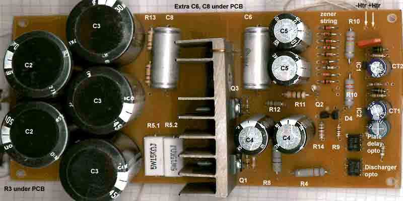
The anode source starts with a fast hex-fred rectifier and a choke input. A small capacitance at the input (0-4 uF) allows you to adjust the output voltage without changing the inductive nature of the filter. A parametric stabilizer with a zener diode current source is a typical solution, for example, from Conrad Johnson.

(click to enlarge)
Changes in the circuit - the LED of the left according to the optocoupler circuit is connected in parallel to the second one (to the output of the time relay).
Automation is powered by a filament rectifier. Charging of the filter capacitances starts immediately after the power is turned on. And the stabilizer is turned off until the relay on ST1-IC1 and the normally closed optocoupler (KR293KP9V) turns on and allows C6 to be charged through the current source on D4-Q2 (I don’t remember exactly what transistors there are). Until this happens, the second (normally open) half of KR293KP9A allows the flow of current through the discharge chain on Q1 (highlighted in blue frame) - in order to avoid excess voltage on the filter capacitances. When turned off, the time-setting capacitance CT1 quickly discharges through the filaments, the relay turns off, and the discharge chain opens again, discharging the residual voltage on the filter capacitances.
Acknowledgments, links, notes
- Similar stabilizer circuits from Conrad Johnson on the Federico Paoletti website, pi.infn.it/~federico/further.htm
- Chris Brady, teresaudio.com/haven
Publication: klausmobile.narod.ru
 See other articles Section Tube Power Amplifiers.
Read and write useful comments on this article.
<< Back
 Latest news of science and technology, new electronics:
Machine for thinning flowers in gardens
02.05.2024
In modern agriculture, technological progress is developing aimed at increasing the efficiency of plant care processes. The innovative Florix flower thinning machine was presented in Italy, designed to optimize the harvesting stage. This tool is equipped with mobile arms, allowing it to be easily adapted to the needs of the garden. The operator can adjust the speed of the thin wires by controlling them from the tractor cab using a joystick. This approach significantly increases the efficiency of the flower thinning process, providing the possibility of individual adjustment to the specific conditions of the garden, as well as the variety and type of fruit grown in it. After testing the Florix machine for two years on various types of fruit, the results were very encouraging. Farmers such as Filiberto Montanari, who has used a Florix machine for several years, have reported a significant reduction in the time and labor required to thin flowers.
... >>
Advanced Infrared Microscope
02.05.2024
Microscopes play an important role in scientific research, allowing scientists to delve into structures and processes invisible to the eye. However, various microscopy methods have their limitations, and among them was the limitation of resolution when using the infrared range. But the latest achievements of Japanese researchers from the University of Tokyo open up new prospects for studying the microworld. Scientists from the University of Tokyo have unveiled a new microscope that will revolutionize the capabilities of infrared microscopy. This advanced instrument allows you to see the internal structures of living bacteria with amazing clarity on the nanometer scale. Typically, mid-infrared microscopes are limited by low resolution, but the latest development from Japanese researchers overcomes these limitations. According to scientists, the developed microscope allows creating images with a resolution of up to 120 nanometers, which is 30 times higher than the resolution of traditional microscopes. ... >>
Air trap for insects
01.05.2024
Agriculture is one of the key sectors of the economy, and pest control is an integral part of this process. A team of scientists from the Indian Council of Agricultural Research-Central Potato Research Institute (ICAR-CPRI), Shimla, has come up with an innovative solution to this problem - a wind-powered insect air trap. This device addresses the shortcomings of traditional pest control methods by providing real-time insect population data. The trap is powered entirely by wind energy, making it an environmentally friendly solution that requires no power. Its unique design allows monitoring of both harmful and beneficial insects, providing a complete overview of the population in any agricultural area. “By assessing target pests at the right time, we can take necessary measures to control both pests and diseases,” says Kapil ... >>
| Random news from the Archive Headphones Logitech G Fits
22.09.2022
Logitech introduced the G-Fits wireless headphones. They are positioned as a gaming solution and support not only Bluetooth connection, but also Lightspeed high-speed wireless technology.
An interesting feature of the device is the ability to take the shape of the ear of its owner. Thanks to Lightform technology, G Fits silicone eartips melt and fill the ear space, taking on its individual form. You can control the process through a special application, you only need to adjust the shape of the ear cushion once. As a result, the headphones provide high-quality protection against external noise, and also will not fall out.
Logitech G Fits have seven hours of battery life on a single charge when connected via LightSpeed and ten hours when using Bluetooth, with the charging case extending that time by eight and twelve hours, respectively. Speech clarity is ensured by two microphones in each earpiece. The model is available in black and white.
The Logitech G Fits will be available in October for $229,99.
|
Other interesting news:
▪ One drop of blood is enough for diagnosis
▪ Notebooks Honor MagicBook X
▪ Efficient artificial photosynthesis
▪ Cafe visitors are served by robots
▪ Keyboard and mouse are the best indicators of stress
News feed of science and technology, new electronics
 Interesting materials of the Free Technical Library:
▪ section of the Electrician website. PTE. Article selection
▪ article Talking about many things is difficult, and sometimes dangerous. Popular expression
▪ article What is a monsoon? Detailed answer
▪ article electrician. Standard instruction on labor protection
▪ article Capacitor capacitance meter. Encyclopedia of radio electronics and electrical engineering
▪ article VHF frequency synthesizer. Encyclopedia of radio electronics and electrical engineering
Leave your comment on this article:
 All languages of this page
Home page | Library | Articles | Website map | Site Reviews

www.diagram.com.ua
2000-2024


 Arabic
 Bengali
 Chinese
 English
 French
 German
 Hebrew
 Hindi
Hindi Italian
 Japanese
 Korean
 Malay
Malay Polish
 Portuguese
 Spanish
 Turkish
 Ukrainian
 Vietnamese
