|
|
ENCYCLOPEDIA OF RADIO ELECTRONICS AND ELECTRICAL ENGINEERING Digital auto-angle controller O3. Encyclopedia of radio electronics and electrical engineering
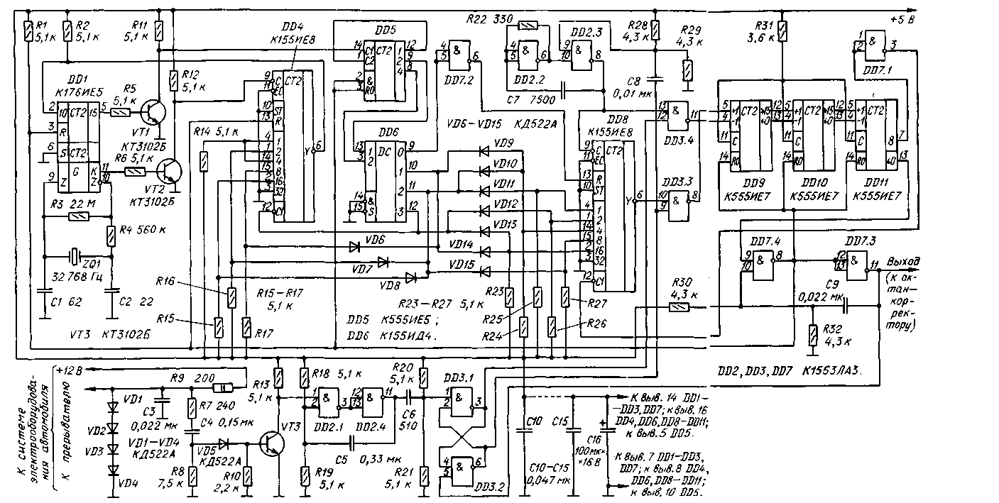
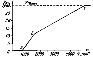
Encyclopedia of radio electronics and electrical engineering / Automobile. Ignition In internal combustion engines of most modern cars, the current ignition timing (03) is controlled mainly by a mechanical centrifugal regulator, which has such disadvantages as characteristic instability and difficulty in changing it, inertia, O3 angle instability caused by friction and backlash in the mechanism. The electronic device offered to the attention of readers is practically free from these shortcomings. Due to its "design flexibility" it can replace any centrifugal governor. By the way, the relevance of this topic has now suddenly increased. The fact is that in recent years, many cars have been imported into Russia, equipped with electronic ignition control units, which fail from time to time. Their replacement in our conditions is not always technically possible, not to mention the fact that it is extremely expensive. The way out of this kind of difficulty in some cases may be the installation of home-made blocks, similar to the one described in this article. The technical characteristics of the digital automatic angle controller 03 described below are highly stable and independent of the ambient temperature. Possible fluctuations of the angle at a fixed frequency of rotation of the crankshaft of the engine do not go beyond ±0,25 degrees. The angle correction occurs every half a turn of the crankshaft of the engine, which practically ensures the inertia of the device. The digital regulator is designed to work in conjunction with the digital octane corrector described by me earlier ("Radio", 1987, No. 10, pp. 34-37), but it can also work independently. The principle of operation of the digital regulator is based on filling the reversible counter with pulses, the repetition rate of which depends on the engine crankshaft speed, and subtracting fixed frequency pulses from it. Writing to the counter begins at the moment of sparking, and subtracting from it - at the moment the breaker contacts open. When the counter goes to state 0, an output pulse is generated that starts the ignition system, after which the process is repeated. The subtraction time determines the delay time of the output pulse relative to the moment of opening the breaker contacts, i.e. the delay angle introduced by the regulator. The schematic diagram of the digital controller is shown in fig. 1. The device consists of a node VT3, DD2.1, DD2.4, which eliminates the influence of the "bounce" of the breaker contacts, a quartz timer DD1, VT1, VT2, DD4-DD6, encoders on diodes VD6-VD15, which determine the characteristic of the regulator, the generator of rectangular pulses DD2.2, DD2.3, counter DD8 with variable counting rate, RS-trigger DD3.1, DD3.2, reversible counter DD9-DD11 and controls. When shown in Fig. In diagram 1 of switching on the VD6-VD15 diodes, the regulator is similar in characteristics to the R-147A mechanical centrifugal regulator, which is installed on some of the M-2140 and M-2141 cars. After the ignition is turned on, the RS-trigger DD3.1, DD3.2 can be set to any state. Let's assume that the output of the element DD3.2 will be high. Then pulses with a frequency of about 50 kHz from the output of the generator DD2.2, DD2.3 after division by the counter DD8 will go to the +1 input of the reversible counter DD9-DD11. When a high-level signal appears at output 8 of counter DD11, element DD7.1 will prohibit the passage of pulses to output Y of counter DD8 and the reversible counter will stop filling. The number of pulses counted by the reversible counter will determine the maximum delay time of the output signal relative to the moment the breaker contacts open. After opening the breaker contacts, the single vibrator DD2.1, DD2.4 will generate a low-level pulse with a duration of about 500 μs, which is necessary to eliminate the influence of the "bounce" of the breaker contacts when they are opened. Differentiated chain C6, R20, R21, this pulse will switch the trigger DD3.1, DD3.2. The high level that appears at the output of the element DD3.1 will allow the passage of the pulses of the generator DD2.2, DD2.3 to the input -1 of the reversible counter, and the low level at the output of the element DD3.2 will prohibit their passage to the input +1. The differentiating circuit C8R28R29 is used to synchronize the generator with the breaker contacts. When switching the reversible counter DD9-DD11 from state 0 to state 15, a low-level pulse will be generated at the output 0 of the counter DD11. The front of this pulse triggers a single vibrator assembled on the elements DD7.4, DD7.3. A high-level pulse from the output of the DD7.4 element will reset the reversible counter and counters DD1, DD4, DD5, and a low-level pulse (about 20 μs long) from the output of the DD7.3 element returns the trigger DD3.2, DD3.1 to its original state. Since the counter DD5 is in the zero state, the output 0 of the decoder DD6 will be a low level signal, which, after being inverted by the element DD7.2, will reset the counter DD8 and keep it in this state. Therefore, while a low level signal is present at the output 0 of the decoder DD6, the reversible counter DD9-DD11 will not be filled, despite the high level at the lower input of the element DD3.3 according to the circuit, and the reversible counter will be in state 0. The time during which the decoder DD6 is in each of the states 0,1,2,3 is determined by the counting factor of the counter DD4, which, in turn, is determined by the current state of the decoder DD6, and the connection diagram of the diodes VD6 -VD8. The counting coefficient of the counter DD8 is also determined by the state of the decoder DD6 and the connection diagram of the diodes VD9-VD15. Consider the formation of the characteristics of the controller, shown in Fig. 2. The article already mentioned above describes the principle of forming the characteristic of an octane corrector. It also includes a reversible counter, but the frequency of filling and subtracting pulses does not change during one period of sparking. In this case, the delay angle introduced by the device is constant and does not depend on the speed of the motor shaft. The characteristic of the octane corrector is a horizontal straight line.
In the electronic automatic angle controller 03, the frequency of the pulses filling the reversible counter changes discretely during one period of sparking, and the graph of the dependence of the angle 03 on the engine shaft speed takes the form of a curve consisting of straight segments. The position of the break points 1, 2, 3 depends on the time intervals during which the decoder DD6 is in each of the states 0, 1,2, 3. The intervals are determined by the counting factor of the counter DD4, which, in turn, depends on the switching circuit of the diodes VD6 -VD8. The pulse repetition rate that fills the reversible counter while the decoder DD6 is in each of the states depends on the counting coefficient of the counter DD8, which is determined by the switching circuit of the diodes VD9 -VD15. In accordance with the regulator circuit (see Fig. 1), when the engine speed is more than 5000 min-1 or the sparking period is less than 6 ms, the decoder DD6 will be in state 0. Therefore, at the input R of the counter DD8 there will be a high level, pulses on it there will be no output, the state of the reversible counter DD9-DD11 does not change, so the controller does not delay the output pulse relative to the input. When the engine shaft speed decreases (see point 1 in Fig. 2), the DD6 decoder switches to state 1, a low level appears at the input R of the counter DD8, the reversible counter starts filling, therefore, the output pulse will be delayed relative to the moment the breaker contacts open. By changing the switching circuit of the diodes VD6-VD8 and VD9-VD15, it is possible to change the characteristic of the electronic regulator over a wide range. The calculation of the counting coefficients of the counters DD4 and DD8, and hence the definition of the decoder circuit, is rather complicated (the size of the journal article does not allow it to be given in full). For their calculation, program (Table 1) in the programming language "Q-Basic", which is included in OCDPS 6.22 and Windows'95. By making minor changes to the program, it can be used on computers "Radio 86RK" and "Spectrum". To run the program, you must enter the characteristics of the centrifugal regulator of the desired model, taken from the technical description of the regulator. This is the angle 03 and the speed of the motor shaft (not to be confused with the speed of the chopper cam) at points 1, 2, 3 of the characteristic (Fig. 2). The result of the program is displayed in a form similar to that presented here in Table 2. Table 2 For example, when the decoder DD6 is in state 2, the required count ratio of the counter DD8 turned out to be 18/64. The maximum ratio of the K155IE8 counter is 63/64. To obtain the desired counting coefficient, it is necessary to apply a low level voltage from output 2 of the DD6 decoder to those inputs of the counter, the sum of the weight values \u63b\u18bof which is equal to 45-1=4, i.e. to inputs 8, 32, XNUMX and XNUMX. The remaining inputs must be at a one level. This is ensured by the inclusion of diodes VD10, VD11 and VD15. At the input 32 counter DD8 low level filed constantly. In table. 2 shows the counting coefficients of the counters DD4 and DD8 and the codes at their inputs for various states of the decoder DD6 to obtain the characteristics of the centrifugal regulator R-147A of the Moskvich-2140 car. Author: A. Biryukov, Moscow; Publication: N. Bolshakov, rf.atnn.ru
Air trap for insects
01.05.2024 The threat of space debris to the Earth's magnetic field
01.05.2024 Solidification of bulk substances
30.04.2024
▪ Earth's composition differs from potentially habitable planets ▪ Small dogs live twice as long as big dogs ▪ HEP-100/150/185 - power supplies for harsh environments
▪ site section Electrician's tool. Article selection ▪ article Anesthesiology and resuscitation. Crib ▪ article Why do photographers say: A bird is about to fly out!? Detailed answer
Home page | Library | Articles | Website map | Site Reviews www.diagram.com.ua |


 Arabic
 Bengali
 Chinese
 English
 French
 German
 Hebrew
 Hindi
Hindi Italian
 Japanese
 Korean
 Malay
Malay Polish
 Portuguese
 Spanish
 Turkish
 Ukrainian
 Vietnamese


 Leave your comment on this article: