|
|
ENCYCLOPEDIA OF RADIO ELECTRONICS AND ELECTRICAL ENGINEERING A device for listening to magnetic phonograms. Encyclopedia of radio electronics and electrical engineering
Encyclopedia of radio electronics and electrical engineering / Audio equipment Among the readers of the magazine "Radio", for sure, there are radio amateurs who would like to listen to magnetic phonograms without disturbing others. I bring to their attention a description of a very simple device that allows you to listen to magnetic recordings, being at a distance of up to 30 m from the tape recorder, that is, anywhere in the apartment or in the courtyard of a private house. The device consists of a transmitter and receiver operating in the 27 MHz band. The receiver is powered by the Krona battery, and the transmitter is powered by the power supply of the tape recorder, although an autonomous power supply can also be used for it.
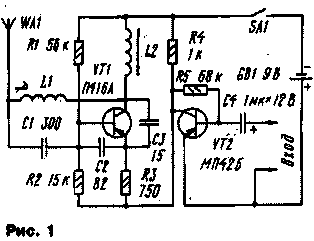
The schematic diagram of the transmitter is shown in fig. 1. It consists of an RF generator assembled on a VT1 transistor and a 3-stage single-stage amplifier on a VT2 transistor. The input of the latter receives a signal from the linear output of the playback amplifier of the tape recorder. This signal modulates the amplitude of the carrier signal of the transmitter oscillator (27,12 MHz), which is emitted by the WA1 antenna.
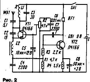
The receiver (Fig. 2) includes a super-regenerative detector based on a VT1 transistor and a 3-stage single-stage amplifier based on a VT2 transistor. The receiver input circuit is tuned to the transmitter frequency of 27,12 MHz. The signal received by the receiver antenna is detected, amplified by a 3-hour amplifier and reproduced by the phone. The transmitter is housed in a tape cassette case, the dimensions of the receiver case are somewhat larger. In both designs, fixed resistors MLT-0,125 are used, the tuning resistor of the receiver R2 is SDR-1. Transmitter capacitors C1 - C3 - K10-7V, oxide capacitor C4 - K50-6 (K50-3 and K50-12 can be used). In the receiver, capacitors C1 - C4, C7 - KG, C6 - KLS, oxide capacitors C5, C8 - the same as in the transmitter. Instead of transistors P416A, P416B, you can use P403, P422 with a static base current transfer coefficient of at least 75 for the receiver and at least 60 for the transmitter. The MP42B transistor can be replaced by any of the MP39, MP40 and MP41 series. Coils L1 both in the transmitter and in the receiver are wound on polystyrene frames with a diameter of 7 mm. They have trimmers made of 600NN ferrite with a diameter of 2,8 and a length of 12 mm. The windings of the coils contain 8,5 turns of wire PEV-2 0,15, wound round to round at the base of the frame. L2 inductors are wound on MLT-0,5 resistor cases with a resistance of at least 500 kOhm. The transmitter inductor winding should contain 80 ... 85 turns of wire PEV-2 0,12, and the receiver inductor winding - 30 turns of the same wire. Switches SA1 - any small-sized. A steel elastic wire 200 mm long was used as receiving and transmitting antennas. Phone-TON-1 or TON-2. Before setting up the equipment, it is necessary first of all to check the operability of the 3H amplifier and the generator B4 of the transmitter. Then, in the receiver, with a tuning resistor R2, set a voltage of 2 V on the emitter of the transistor VT6 relative to the common wire and measure the current consumed from the battery. It should be within 12...15 mA. The deviation of the current value, both up and down, indicates an error in the installation or a malfunction of any part. Now proceed directly to the configuration. To do this, connect the input of the AF transmitter amplifier to the output of the playback amplifier of the tape recorder. Then they put a cassette on the tape recorder and turn on the tape recorder and transmitter. Lastly, turn on the receiver and, using the trimmers of the L1 coils of the transmitter and receiver, tune their oscillatory circuits to the same frequency, achieving the loudest sound in phones. During tuning, the receiver must be at a distance of 5 m from the transmitter. After adjustments, the trimmers of the coils are strengthened with paraffin. Author: A. Gridnev, Vladikavkaz; Publication: N. Bolshakov, rf.atnn.ru
Machine for thinning flowers in gardens
02.05.2024 Advanced Infrared Microscope
02.05.2024 Air trap for insects
01.05.2024
▪ Network video intercom Axis A8004-VE ▪ Canadian military snowmobile ▪ Found evidence of the existence of exotic quark matter
▪ section of the website Residual current devices. Selection of articles ▪ Fleming Alexander article. Biography of a scientist ▪ article Land sailing ship. Personal transport ▪ article Unbreakable handkerchief. Focus Secret
Home page | Library | Articles | Website map | Site Reviews www.diagram.com.ua |


 Arabic
 Bengali
 Chinese
 English
 French
 German
 Hebrew
 Hindi
Hindi Italian
 Japanese
 Korean
 Malay
Malay Polish
 Portuguese
 Spanish
 Turkish
 Ukrainian
 Vietnamese


 Leave your comment on this article: