|
|
ENCYCLOPEDIA OF RADIO ELECTRONICS AND ELECTRICAL ENGINEERING Band pass filter. Encyclopedia of radio electronics and electrical engineering
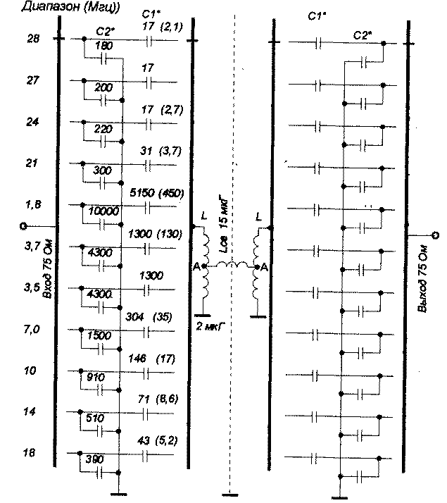
Encyclopedia of radio electronics and electrical engineering / Knots of amateur radio equipment. Filters and matching devices Bandpass filter (BFT), shown in Fig. 1, is a more advanced design of the filter, published earlier in the journal "Radioamateur" [1]. The prototype had noticeable losses in the range of 160 meters. In the proposed modification, this shortcoming is eliminated.
The filter bandwidth is determined by the ratio Af=l,4f/Qe, where f is the center frequency of the range; Qe - quality factor of the circuit. For calculation on all amateur bands, it is chosen equal to 30. Due to the high quality factor of the circuits in the 80 m range, the filter bandwidth is approximately 150 kHz, so it had to be divided into two sub-bands 3,5 - 3,65 MHz and 3,65 - 3,8 MHz.
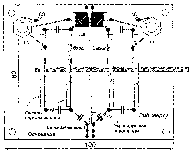
The DFT contains only two main coils, which makes it possible to significantly reduce its overall dimensions and not to make shielding between the elements of the ranges. It is possible to offer two options for the circuit design of the DPF - to switch the ranges with biscuit switches or small-sized relays RES-60. Figure 3 shows a sketch of the layout of the DFT (author's version), switched by a ceramic 4-way switch. The filter dimensions can be somewhat reduced using PGZ-type switches with a biscuit diameter of about 30 mm. The LCB coupling coil is wound on a rod of insulating material with a diameter of 8 mm. Coils L1 and L2 can be wound on suitable frames with a diameter of 12 ... 20 mm.
To determine the number of turns, it is appropriate to give the calculation formula for a single-layer coil
w is the number of turns; L is the inductance of the coil, μH; 1 - winding length, cm; D is the coil diameter. The filter can be calculated for any frequency, the capacitances of capacitors C1 and C2 are determined by the formulas
where f is the desired operating frequency. The filter is designed for resistance Rin=Kout=75 Ohm. Coil inductance L1 and L2 = 2 μH, LCB = 15 μH. In the DFT version on biscuit switches, it is convenient to place the 10-28 MHz ranges on the petals facing up and to the sides, and make the capacitors C1 composite of parallel-connected trimmer ceramic capacitors KPK-M and ceramic capacitors of constant capacitance. Trimmer capacitors for structural rigidity are installed and soldered on strips of foil fiberglass, which, in turn, are rigidly soldered between the petals of the biscuits. Capacitors C2 are immediately soldered between the switch petals and the ground bus, also made of foil fiberglass, screwed to a vertical carrier screen. The values of the capacitors C2 are chosen closest to the calculated values. When setting up a filter, they are usually not selected. Taps in coils L (point A) are made from the middle. Filter setting The filter is tuned according to the usual method, using a GSS and an RF voltmeter, or, which is much faster and clearer, using a frequency response meter (XI-38, XI-48, etc.). The filter output is loaded with a 75 ohm resistor. The DFT is tuned in two ways. On ranges where trimmer capacitors are installed, the setting is as follows. First, the connection between the circuits L1 and L2 is forcibly weakened - a capacitor is soldered in parallel with the coupling coil, the value of which is approximately equal to 2/3 of the capacitance of the compensating capacitor in each range, they are indicated in brackets in Fig. 1. Thus, each circuit, independently of each other, can be tuned to the middle of the range for the maximum GSS signal. Then the compensating capacitance is removed and the frequency response is taken, which turns out to be shifted higher in frequency. The frequency offset value is determined, the compensating capacitance is soldered again, and the tuning procedure is repeated, but at a lower frequency, taking into account the offset value. After soldering the compensating capacitor, a final check is made of the resulting frequency response. An example of setting the filter to one of the amateur radio bands We tune the 10-meter band at a frequency of 28,5 MHz. Desired bandwidth 27,85 ... 29,15 MHz, center tuning frequency 28,5 MHz. The originally measured bandwidth turned out to be 28,2 ... 29,5 MHz, i.e. shifted up at 350 kHz. Then we re-tuning at the center frequency of 28,15 MHz and the A frequency response of the range is in place. On those ranges where there are no tuning capacitors, it is more convenient to tune in a way that is somewhat different from the previous one. The GSS signal is applied to the DFT input, the RF voltmeter is connected to point A of the tuned circuit, and the opposite point A is grounded. GSS-ohm is determined by the resonant frequency of the primary circuit. By switching the HSS from the input of the DFT to its output, the resonant frequency of the second circuit is determined in a similar way. By selecting the value of the capacitor C2, the second circuit is tuned to the resonant frequency of the first circuit. We restore the filter to its working position, load it with 75 ohms and record the resulting frequency response (see example). We repeat the tuning procedure taking into account the shift frequency, tune the circuit again, selecting capacitors C1 and C2, and correct the final frequency response. DFT into 50 Ohm If you need to make a DFT with Rin \u50d Kout \uXNUMXd XNUMX Ohm, then you can use the following formulas to calculate capacitors
3-loop DFT For those who want to make an even better DFT, with a greater steepness of the slopes (it should be noted that in this case, the attenuation in the passband will slightly increase, approx. RW3AY), we can offer a more complicated version. The filter turns into a three-circuit system with more complex switching, Fig.2. The inductance of the middle coil should be half the inductance of the outer coils - 1 μH. In the middle circuit, it is enough to switch only one capacitor on each range. Its value can be determined by the formula С = 2С1С2/С1+С2 Literature
Author: N.Smirnov, UA3TW, Nizhny Novgorod; Publication: N. Bolshakov, rf.atnn.ru
Machine for thinning flowers in gardens
02.05.2024 Advanced Infrared Microscope
02.05.2024 Air trap for insects
01.05.2024
▪ Memory cards with backup function ▪ The bus recognizes the pedestrian
▪ section of the website Audiotechnics. Article selection ▪ article Liquid compositions for cleaning canvas and canvas shoes. Simple recipes and tips ▪ article Babies from the stroller. Focus Secret
Home page | Library | Articles | Website map | Site Reviews www.diagram.com.ua |


 Arabic
 Bengali
 Chinese
 English
 French
 German
 Hebrew
 Hindi
Hindi Italian
 Japanese
 Korean
 Malay
Malay Polish
 Portuguese
 Spanish
 Turkish
 Ukrainian
 Vietnamese


 Leave your comment on this article: