|
|
ENCYCLOPEDIA OF RADIO ELECTRONICS AND ELECTRICAL ENGINEERING Diagram of your receiver. Encyclopedia of radio electronics and electrical engineering
Encyclopedia of radio electronics and electrical engineering / Beginner radio amateur To correctly connect the parts of the receiver, you used the drawings. On them you saw a coil, telephones, a detector and other details and connections as they look in nature. This is very convenient to start with, while you have to deal with very simple radio designs, which include few details. But if you try to depict the device of a modern receiver in this way, you would get such a "web" of wires that would be impossible to understand. To avoid this, any electrical appliance or radio device is depicted schematically, that is, using a simplified drawing - a diagram. This is not only done in electrical and radio engineering. Look, for example, at a geographical map. The navigable mighty beauty of the Volga, with all its grandiose structures, is depicted on the map as a wriggling snake. Such large cities as Moscow, Leningrad, Kuibyshev, Vladivostok, etc. are shown only by circles. Forests, plains, mountains, seas, canals are also depicted on the geographical map in a simplified way - schematically. There are two types of circuits: basic electrical and assembly. Circuit diagrams are usually referred to simply as circuit diagrams. On the circuit diagram, conventional signs depict all the details of a radio engineering device and the order in which they are connected. "Reading" a schematic diagram, like a geographical map or a drawing of some kind of mechanism, it is easy to understand the circuits and the operation of the device. But it does not give an idea of the size and placement of its parts. The wiring diagram, in contrast to the circuit diagram, shows how the parts and connecting conductors are located in the design. When assembling a receiver, amplifier or any other radio device or device, the radio amateur arranges the parts and conductors approximately as in the wiring diagram. But the installation and verification of the correctness of all connections is carried out according to the concept diagram. Being able to read radio circuits is absolutely essential for anyone who wants to become a radio amateur. On fig. 33 you see details and devices already familiar to you and some others that you will have to deal with in the future. And next in the circles - their symbolic graphic images on the circuit diagrams. Any coil without a core, which can be a metal or ferrite rod, regardless of its design and number of turns, is depicted in the diagram as a wavy line. The taps of the coils are shown by dashes. If the coil has a fixed ferrite core that increases its inductance, it is indicated by a thick line along the entire. coils. If the receiver circuit is tuned with such a core, as it was in the experimental receiver, it is indicated in the diagram in the same way, but crossed with an arrow along with the coil.
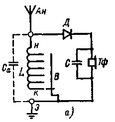
Any capacitor of constant capacitance is depicted by two short parallel lines, symbolizing two plates isolated from one another. Capacitors of variable capacitance are depicted in the same way as capacitors of constant capacitance, but crossed with an oblique arrow, which symbolizes the variability of the capacitance of this device. Sockets for connecting the wire of the antenna, headphones or some other devices or parts are indicated with plug-shaped icons, and clamps (collapsible contacts) with circles. New to you is the switch. Instead of untwisting and twisting the conductors when setting up the receiver, as you did when conducting experiments with the first receiver, the leads and taps of the coil can be connected to the metal contacts located on the receiver panel, and in the future they can be switched by simply moving the switch slider. The conductors that connect the parts are indicated by straight lines. If the lines converge and there is a dot at the point of their intersection, then the conductors are connected. The absence of a dot at the intersection of the conductors indicates that they are not connected. On the circuit diagrams, next to the symbolic designations, they put the letters assigned to these parts or devices. Capacitors are assigned the Latin letter C, resistors (they used to be called resistances) - the Latin letter R, coils - the Latin letter L, head phones - the Russian letters Tf, switches and switches of current sources - the letter B, batteries - the letter B, lamps - L and t If there are several capacitors, coils, resistors or other parts on the diagram, then they are numbered: a number is placed next to the letter, for example, C1, C2, L1, L2, R1, R2. The diagrams sometimes do not show the antenna, grounding, telephones, limiting themselves only to the designations of the clamps or sockets for their connection. Then, next to these clamps or sockets, they put the corresponding letters: AN, Tf. Now, knowing the symbols of the parts, all the variants of the detector receiver with which you experimented, you can depict them with schematic diagrams. A schematic diagram of the first version of the experimental receiver is shown in Fig. 34, a. You tuned the receiver by switching the grounded conductor. Therefore, switch B is introduced into the circuit. Remember our "walk" through the receiver circuits and do it again, but according to the circuit diagram. From the beginning of the coil L you will get to the diode D and through it - to the telephones Tf, then through the telephones along the grounded conductor, the switch B and the turns of the coil L - to the starting point n. This is a detector circuit. For high frequency currents, the path from the antenna to ground is through the turns of the coil and switch B. This is the antenna circuit. Tuning the receiver circuit at the radio station is carried out by a switch by an abrupt change in the number of turns included in the circuit. Blocking capacitor C is connected in parallel with the telephones.
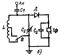
In the diagram, with dashed lines, showing another Ca capacitor. There was no such part in the receiver. But the electrical capacitance symbolizing it was present - it was formed by an antenna and grounding and, as it were, was connected to a tuned circuit. A schematic diagram of the second version of the experimental receiver is shown in fig. 34b. Its input tuned circuit consists of a coil L, which has one tap, a variable capacitor C2 of the antenna device that you introduced, and an antenna capacitor C1. The inclusion in the circuit of the upper section of the coil corresponds to the reception of radio stations of the medium wave range, and both sections - to the reception of radio stations of the long wave range. Thus, in the receiver, the transition from one range to another is carried out by switch B, and smooth tuning in each range is carried out by a variable capacitor C2. The third option was a receiver tuned by a ferrite rod. A schematic diagram of such a receiver is shown in Fig. 34, c. He, as you can see, is single-range. To receive radio stations of a different range, the coil L must be replaced, which you did when conducting experiments with this receiver. TF jacks are provided for connecting headphones. Publication: N. Bolshakov, rf.atnn.ru
Alcohol content of warm beer
07.05.2024 Major risk factor for gambling addiction
07.05.2024 Traffic noise delays the growth of chicks
06.05.2024
▪ Canada to build accurate dark matter detector ▪ Microcontrollers Texas Instruments MSP432 ▪ Neural interface for controlling work with the power of thought ▪ TPA6211A1 - audio amplifier chip
▪ section of the site For a beginner radio amateur. Article selection ▪ Polyethylene article. History of invention and production ▪ article What does a language do? Detailed answer ▪ article Caretaker of the cemetery (columbarium). Job description ▪ article Symmetric multivibrator. Encyclopedia of radio electronics and electrical engineering ▪ article Riddles about a person
Comments on the article: Kuznetsov Igor Nikolaevich The library is wonderful. There is a wish - it would be nice to do downloads via torrent.
Home page | Library | Articles | Website map | Site Reviews www.diagram.com.ua |


 Arabic
 Bengali
 Chinese
 English
 French
 German
 Hebrew
 Hindi
Hindi Italian
 Japanese
 Korean
 Malay
Malay Polish
 Portuguese
 Spanish
 Turkish
 Ukrainian
 Vietnamese


 Leave your comment on this article: