|
|
ENCYCLOPEDIA OF RADIO ELECTRONICS AND ELECTRICAL ENGINEERING Oscillatory circuit. Encyclopedia of radio electronics and electrical engineering
Encyclopedia of radio electronics and electrical engineering / Beginner radio amateur The device and diagram of the simplest oscillatory circuit are shown in Fig.1. It, as you can see, consists of a coil L and a capacitor C, forming a closed electrical circuit. Under certain conditions, electrical oscillations can arise and exist in the circuit. Therefore, it is called an oscillatory circuit. Have you ever observed such a phenomenon: at the moment of turning off the power of an electric lighting lamp, a spark appears between the opening contacts of the switch. If you accidentally connect the battery strips of an electric flashlight (which should be avoided), at the moment they are separated, a small spark also jumps between them. And in power plants, in factories where electric circuits are broken by switches, through which very large currents flow, sparks can be so significant that measures must be taken so that they do not harm the person who turns on the current. Why are these sparks generated?
From the first conversation, you already know that there is a magnetic field around a current-carrying conductor, which can be depicted as closed magnetic lines of force penetrating the surrounding space (Fig. 2). To detect this field, if it is constant, you can use the magnetic needle of the compass. If the conductor is disconnected from the current source, then its disappearing magnetic field, dissipating in space, will induce currents in other conductors. The current is induced in the conductor that created this magnetic field. And since it is in the very thick of its own magnetic lines of force, a stronger current will be induced in it than in any other conductor. The direction of this current will be the same as it was at the moment of breaking the conductor. In other words, a disappearing magnetic field will maintain the current that created it until it disappears itself, i.e., the energy contained in it is not completely used up. Consequently, the current in the conductor also flows after the current source is turned off, but, of course, not for long - a negligible fraction of a second.
But in an open circuit, the movement of electrons is impossible, you will object. Yes it is. But after the circuit is opened, electric current may flow for some time through the air gap between the disconnected ends of the conductor, between the contacts of the switch or knife switch. This current through the air forms an electric spark. This phenomenon is called self-induction, and the electric force (do not confuse with the induction, which we talked about in the first conversation), which, under the influence of a vanishing magnetic field, maintains a current in it, is the electromotive force of self-induction or, in short, emf. self-induction. The more emf. self-induction, the more significant the spark can be at the point of breaking the electrical circuit. The phenomenon of self-induction is observed not only when the current is turned off, but also when the current is turned on. In the space surrounding the conductor, a magnetic field arises immediately when the current is turned on. At first it is weaker, but then it intensifies very quickly. The increasing magnetic field of the current also excites the self-induction current, but this current is directed towards the main current. The self-induction current prevents the instantaneous increase in the main current and the growth of the magnetic field. However, after a short period of time, the main current and the conductor overcomes the oncoming self-induction current and reaches its maximum value, the magnetic field becomes unchanged and the self-induction stops. The phenomenon of self-induction can be compared with the phenomenon of inertia. Sledges, for example, are difficult to budge. But when they gain speed, they stock up on kinetic energy - the energy of movement, they cannot be stopped instantly. After braking, they continue to slide until the energy of movement stored by them is used up to overcome friction on the snow. Do all conductors have the same self-inductance? Not! The longer the conductor, the greater the self-induction. In a conductor wound into a coil, the phenomenon of self-induction is more pronounced than in a straight conductor, since the magnetic field of each turn of the coil induces current not only in this turn, but also in neighboring turns of this coil. The longer the wire in the coil, the longer the self-induction current will exist in it after the main current is turned off. And, on the contrary, it will take longer times to turn on the main current, so that the current in the circuit rises to a certain value and a magnetic field of constant strength is established. Remember: the property of conductors to influence the current in the circuit when its value changes is called inductance, and the coils in which this property is most pronounced are self-induction or inductance coils. The greater the number of turns and the dimensions of the coil, the greater its inductance, the greater its influence on the current in the electric; chains. So, the coil prevents both the increase and decrease of current in the electrical circuit. If it is in a direct current circuit, its influence affects only when the current is turned on and off. In an alternating current circuit, where the current and its magnetic field are constantly changing, emf. The self-induction of the coil is active as long as the current is flowing. This is an electrical phenomenon and is used in the first element of the receiver's oscillatory circuit - the coil.
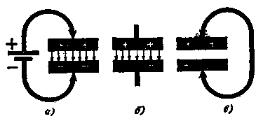
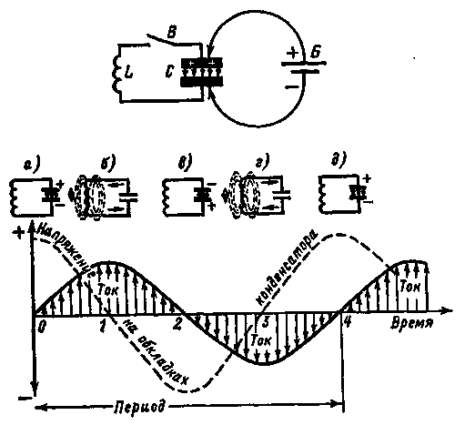
The second element of the oscillatory circuit of the receiver is the "accumulator" of electric charges - a capacitor. The simplest capacitor consists of two conductors of electric current, it can be two metal plates, called capacitor plates, separated by a non-conductor of electric current - a dielectric, such as air or paper. You have already used such a capacitor during experiments with a simple receiver. The larger the area of the capacitor plates and the closer they are located to each other, the greater the electrical capacitance of this device. If a direct current source is connected to the capacitor plates (Fig. 3, a), then a short-term current will appear in the resulting circuit and the capacitor will be charged to a voltage equal to the voltage of the current source. You may ask: why does a current appear in a circuit where there is a dielectric? When we connect a constant current source to the capacitor, free electrons in the conductors of the resulting circuit begin to move towards the positive pole of the current source, forming a short-term flow of electrons throughout the circuit. As a result, the capacitor plate, which is connected to the positive pole of the current source, is depleted in free electrons and is positively charged, while the other is enriched in free electrons, and, therefore, is charged negatively. As soon as the capacitor is charged, the short-term current in the circuit, called the capacitor charge current, will stop. If the current source is disconnected from the capacitor, then the capacitor will be charged (Fig. 3, b). The transfer of excess electrons from one plate to another is prevented by a dielectric. There will be no current between the plates of the capacitor, but accumulated by it. electrical energy will be concentrated in the electrical fraction of the dielectric a. But it is worth connecting the plates of a charged capacitor with a conductor (Fig. 3, c), the "excess" electrons of the negatively charged plate will pass through this conductor to another plate, where they are missing, and the capacitor will be discharged. In this case, a short-term current also occurs in the resulting circuit, called the capacitor discharge current. If the capacitance of the capacitor is large, and it is charged to a significant voltage, the moment of discharge is accompanied by the appearance of a significant spark and crackling. The property of a capacitor to accumulate electric charges and discharge through the conductors connected to it is precisely used in the oscillatory circuit of a radio receiver. And now, young Friend, remember an ordinary swing. You can swing on them so that "it takes your breath away." What needs to be done for this? First push to bring the swing out of rest, and then apply some force, but always only in time with their oscillations. Without much difficulty, you can achieve strong swing swings - get large amplitudes of oscillation. Even a small boy can swing an adult on a swing if he applies his strength skillfully. Having swung the swing harder, in order to achieve large amplitudes of oscillations, we will stop pushing them. What will happen next? Due to the stored energy, they swing freely for some time, the amplitude of their oscillations gradually decreases, as they say, the oscillations die out, and, finally, the swing stops. With free oscillations of a swing, as well as a freely suspended pendulum, the stored - potential - energy turns into kinetic - the energy of movement, which at the highest point again turns into potential, and after a fraction of a second - again into kinetic. And so on until the entire supply of energy is used up to overcome the friction of the ropes in the places where the swing is suspended and air resistance. With an arbitrarily large amount of energy, free oscillations are always damped: with each oscillation, their amplitude decreases and the oscillations gradually completely die out - peace sets in. But the period (the length of time during which one oscillation occurs), and hence the frequency of oscillations, remain constant. However, if the swing is constantly pushed in time with its oscillations B, thereby replenishing the energy losses spent on overcoming various braking forces, the oscillations will become undamped. These are no longer free, but forced oscillations. They will last until the external pushing force ceases to act. I mentioned swings here because the physical phenomena that occur in such a mechanical oscillatory system are very similar to those in an electrical oscillatory circuit. In order for electrical oscillations to arise in the circuit, it must be given energy that would "push" the electrons. This can be done by charging, for example, its capacitor. Let's break the switch B into the oscillatory circuit and connect the DC source to the plates of its capacitor, as shown in Fig. 4 above. The capacitor will be charged to the voltage of battery B. Then we disconnect the battery from the capacitor, and close the circuit with switch C. The phenomena that will now occur in the circuit are shown graphically in Fig. 4 below.
When the circuit is closed by a switch, the upper plate of the capacitor has a positive charge, and the lower one has a negative charge (Fig. 4, a). At this moment, marked on the graph by point O, there is no current in the circuit, and all the energy accumulated by the capacitor is concentrated in the electric field between its plates. But the capacitor is closed to the coil, through which it will begin to discharge. A current appears in the coil, and a magnetic field appears around its turns. By the time the capacitor is completely discharged (Fig. 4, b), marked on the graph by the number 1, when the voltage on its plates drops to zero, the current in the coil and the energy of the magnetic field will reach the highest values. It would seem that at this moment the current in the circuit should have stopped. This, however, will not happen, since from the action of the emf. self-induction, seeking to maintain the current, the movement of electrons in the circuit will continue. But only until all the energy of the magnetic field is used up. In the coil at this time, an induced current of decreasing magnitude, but of the original direction, will flow. By the time point marked on the graph by the number 2, when the energy of the magnetic field is used up, the capacitor will again be charged, only now there is a positive charge on its lower plate, and a negative charge on the upper one (Fig. 4, c). Now the electrons will begin to reverse movement in the direction from the top plate through the coil to the bottom plate of the capacitor. By time 3 (Fig. 4, d) the capacitor will be discharged, and the magnetic field of the coil will reach its maximum value. And again, emf. self-induction will "drive" electrons through the coil wire, thereby recharging the capacitor. At time 4 (Fig. 4, e) there will be the same state of electrons in the circuit as at the initial moment 0. One complete oscillation has ended. Naturally, the charged capacitor will again be discharged into the coil, recharged, and the second will occur, followed by the third, fourth, etc. fluctuations. In other words, an alternating electric current, electrical oscillations, will appear in the circuit. But this oscillatory process in the circuit is not infinite. It continues until all the energy received by the capacitor from the battery is used up to overcome the resistance of the coil wire of the circuit. Such oscillations in the circuit are free B, and therefore damped. What is the frequency of these oscillations of electrons in the circuit? To better understand this issue, I advise you to conduct such an experiment with the simplest pendulum. Suspended on a thread, 100 cm long, a ball molded from plasticine, or another load weighing (weight) 20-40 g (in Fig. 5, the length of the pendulum is indicated by the Latin letter l). Take the pendulum out of equilibrium and, using a clock with a second hand, count how many complete oscillations it makes in 1 minute. Approximately 30. Therefore, the oscillation frequency of this pendulum is 0,5 Hz, and the period is 2 s. During the period, the potential energy of the pendulum twice passes into the kinetic, and the kinetic into the potential. Cut the thread in half. The frequency of the pendulum will increase by about one and a half times and the oscillation period will decrease by the same amount.
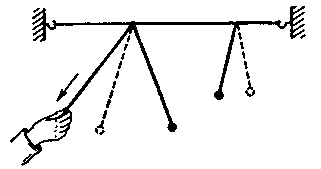
This experience allows us to conclude: with a decrease in the length of the pendulum, the frequency of its natural oscillations increases, and the period decreases proportionally. By changing the length of the pendulum suspension, make sure that its oscillation frequency is 1 Hz. This should be with a thread length of about 25 cm. In this case, the period of oscillation of the pendulum will be equal to 1 s. No matter how you try to create the initial swing of the pendulum, the frequency of its oscillations will be unchanged. But one has only to shorten or lengthen the thread, as the oscillation frequency will immediately change. With the same thread length, there will always be the same oscillation frequency. This is the natural frequency of the pendulum. It is possible to obtain a given oscillation frequency by selecting the length of the thread. The oscillations of the thread pendulum are damped. They can become undamped only if the pendulum is slightly pushed in time with its oscillations, thus compensating for the energy that it expends on overcoming the resistance exerted by the air, the energy of friction, the earth's gravity. An electrical oscillatory circuit also has its own frequency. The natural oscillation frequency depends, firstly, on the inductance of the coil. The greater the number of turns and the diameter of the coil, the greater its inductance, the greater will be the duration of the period of each oscillation. The natural frequency of oscillations in the circuit will be correspondingly less. And, conversely, with a decrease in the inductance of the coil, the period of oscillation will be reduced - the natural frequency of oscillation in the circuit will increase. The frequency of oscillations in the circuit depends, secondly, on the capacitance of the capacitor. The larger the capacitance, the more charge the capacitor can accumulate, the more time it will take to recharge it, and this will reduce the frequency of oscillations in the circuit. With a decrease in the capacitance of the capacitor, the frequency of oscillations and the circuit increases. Thus, the natural frequency of damped oscillations in the circuit can be controlled by changing the inductance of the coil or the capacitance of the capacitor. But in an electric circuit, as well as in a mechanical oscillatory system, undamped ones can also be obtained, i.e. forced oscillations, if at each oscillation the circuit is replenished with additional portions of electrical energy from any source of alternating current. How, then, are undamped electrical oscillations excited and maintained in the receiver circuit? High frequency current excited in the antenna. This current informs the circuit of the initial charge, and it also maintains the rhythmic oscillations of the electrons in the circuit. However, the strongest undamped oscillations in the receiver circuit occur only at the moment of resonance of the natural frequency of the circuit with the frequency of the current in the antenna. What does it mean? People of the older generation say that in St. Petersburg, the Egyptian bridge collapsed from soldiers walking in step. And it could happen, apparently, under such circumstances. All the soldiers paced rhythmically across the bridge. The bridge began to sway from this - to oscillate. By a coincidence, the natural frequency of the bridge coincided with the step frequency of the soldiers, as they say, the bridge fell into resonance. The rhythm of the building informed the bridge more and more portions of energy. As a result, the bridge swayed so much that it collapsed: the coherence of the military system harmed the bridge. If there were no resonance of the natural oscillation frequency of the bridge with the step frequency of the soldiers, nothing would have happened to the bridge. Therefore, by the way, when soldiers pass over weak bridges, it is customary to give the command to "knock off the leg." And here is the experience. Go to some stringed musical instrument and shout loudly "a": one of the strings will respond, sound. The one that is in resonance with the frequency of this sound will vibrate more strongly than the other strings - it will respond to the sound. Another experience - with pendulums. Stretch a thin rope horizontally. Tie the same pendulum made of thread and plasticine to it (Fig. 6). Throw another similar pendulum over the rope, but with a longer thread. The length of the suspension of this pendulum can be changed by pulling the free end of the thread by hand. Bring this pendulum into oscillatory motion. In this case, the first pendulum will also begin to oscillate, but with a smaller amplitude. Without stopping the oscillations of the second pendulum, gradually reduce the length of its suspension - the amplitude of oscillations of the first pendulum will increase. In this experiment, illustrating the resonance of mechanical vibrations, the first pendulum is the receiver of vibrations excited by the second pendulum. The reason forcing the first pendulum to oscillate is periodic oscillations of the extension with a frequency equal to the oscillation frequency of the second pendulum. Forced oscillations of the first pendulum will have a maximum amplitude only when its natural frequency coincides with the oscillation frequency of the second pendulum.
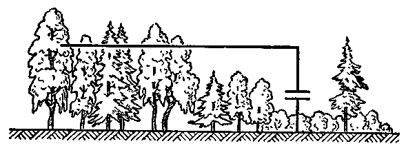
Such or similar phenomena, only, of course, of electrical "origin", are also observed in the oscillatory circuit of the receiver. From the action of the waves of many radio stations, currents of various frequencies are excited in the receiving antenna. From all these frequencies, we need to choose only the frequency of the radio station whose transmissions we want to listen to. To do this, you should choose the number of turns of the coil and the capacitance of the capacitor of the oscillatory circuit so that its natural frequency coincides with the frequency of the current created in the antenna by the waves of the station of interest to us. In this case, the strongest oscillations will be excited in the circuit with the carrier frequency of the radio station to the wave of which it is tuned. This is the tuning of the receiver circuit into resonance with the frequency of the transmitting station. In this case, the signals of other stations are not audible at all or are heard very weakly, since the oscillations excited by them in the circuit will be very weak. Thus, by tuning the circuit of your first receiver to resonance with the frequency of the radio station, with its help you, as it were, selected, singled out the frequency fluctuations of only this station. The better the circuit will select the desired oscillations from the antenna, the higher the selectivity of the receiver, the weaker the interference from other radio stations will be. Until now, I have told you about a closed oscillatory circuit, i.e. circuit, the natural frequency of which is determined only by the inductance of the coil and the capacitance of the capacitor forming it. However, the input circuit of any receiver also includes an antenna and ground. This is no longer a closed, but an open oscillatory circuit. The fact is that the antenna wire and the Earth are "plates" of a capacitor (Fig. 7), which has a certain electrical capacitance. Depending on the length of the wire and the height of the antenna above the ground, this capacitance can be up to several hundred picofarads. Such a capacitor in the circuit of Fig. was shown with dashed lines. But after all, the antenna and the earth can also be considered as an incomplete coil of a large coil. Therefore, the antenna and ground, taken together, also have inductance. And the capacitance together with the inductance form an oscillatory circuit.
Such a circuit, which is an open oscillatory circuit, also has its own oscillation frequency. By including inductors and capacitors between the antenna and ground, we can change its natural frequency, tune it into resonance with the frequencies of different radio stations. How this is done in practice, you already know. I will not be mistaken if I say that the oscillatory circuit is the "heart" of the radio receiver. And not just the radio. You will be convinced of this. That's why I paid a lot of attention to him. Publication: N. Bolshakov, rf.atnn.ru
Traffic noise delays the growth of chicks
06.05.2024 Wireless speaker Samsung Music Frame HW-LS60D
06.05.2024 A New Way to Control and Manipulate Optical Signals
05.05.2024
▪ Electric current against fouling ▪ Japan to build a network of orbital energy platforms ▪ Liquid Cooled TeamGroup M.2 SSD ▪ Paper airplane with laser engine
▪ section of the site Electricity for beginners. Article selection ▪ article How does anyone bake pancakes. Popular expression ▪ article Why is the body warm? Detailed answer ▪ article Work on rewinders. Standard instruction on labor protection ▪ article Soldering without overheating. Encyclopedia of radio electronics and electrical engineering
Home page | Library | Articles | Website map | Site Reviews www.diagram.com.ua |


 Arabic
 Bengali
 Chinese
 English
 French
 German
 Hebrew
 Hindi
Hindi Italian
 Japanese
 Korean
 Malay
Malay Polish
 Portuguese
 Spanish
 Turkish
 Ukrainian
 Vietnamese


 Leave your comment on this article: