
|
|
ENCYCLOPEDIA OF RADIO ELECTRONICS AND ELECTRICAL ENGINEERING Designs of VHF circuits. Encyclopedia of radio electronics and electrical engineering
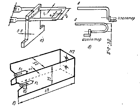
Encyclopedia of radio electronics and electrical engineering / radio reception In the ranges of 144 and 430 MHz and above, either open circuits of two-wire lines or coaxial circuits are most often used. Newer types - flat and grooved contours - have not yet found wide distribution. The main attention in the implementation of any contours on VHF is to reduce all types of losses. High-frequency currents go mainly along the outer surface of the conductor, the depth of their penetration inside is very small and depends on the conductivity of the material and frequency. So, for copper, the most common material, the penetration depth at a frequency of 300 MHz will be 0,0038 mm, and at a frequency of 500 MHz - 0,003 mm. It should be borne in mind that brass and duralumin create losses twice as large as copper. It is desirable to silver brass products. For contours, it is advantageous to use smooth thin-walled steel tubes, if possible, it is desirable to chrome them. For coaxial circuits and two-wire lines, copper is the best material. The small depth of penetration of currents on VHF requires that the surfaces be smooth, polished to a mirror finish, since any roughness is equivalent to an increase in surface resistance and RF losses. To prevent oxidation of copper, it is coated with silver or colorless varnish (parts where there are no sliding contacts). The manufacture of circuits depends on the type of lamp and the purpose of the device. The most suitable lamps for the 144 MHz range are GU-32, GU-29, 6P21S, GU-50 and it is easier to use two-wire lines for them. For decimeter ranges, special lamps of the 6S5D type are good, the so-called beacon, metal-ceramic GI11B, GI12, and 6S11D - disk, decimeter. The qualities of these lamps can only be fully exploited with the use of coaxial lines. Figures 1 and 2 show the largest nodes of the two-wire circuits in relation to the GU-32 lamp. The length of the line should be 250-270 mm, taking into account the additional capacity of the trimmer capacitor, the distance between the wires D = 25 mm is determined by the distance between the leads of the anodes, the diameter of the wire or tube d = 4-6 mm. It is impractical to use wire or tubes of a larger diameter, they are inconvenient in processing and, in addition, increase the losses in the circuit due to increased radiation, which increases with decreasing D/d. To reduce the longitudinal dimensions, symmetrical lines can be bent in different ways (see Fig. 1b). The wires of the line are fixed to the blocks of insulating material at the short-circuited end and at the middle of the line (see Fig. 1, a).
Flat or ribbon HF lines are very successful. On fig. 1c shows the dimensions of the quarter-wave anode line for the 430 MHz band for a GU-32 lamp operating with a frequency tripler (144-432 MHz). In the design shown in Fig. 1, f, it is assumed that the GU-32 lamp is located perpendicular to the chassis. If it is placed horizontally, this will avoid bending the line at the point of its connection to the anodes and it will be a continuation of the planes of the anode electrodes. To reduce the inhomogeneity of this transition, which is equivalent to introducing an additional capacitance and entails shortening the circuit, triangular recesses are made in the strips where the spring contacts K1 and K2 are soldered. This allows you to move the line close to the lamp bulb along the entire height of the strip and reduce the gap between it and the anodes of the GU-32 lamp.
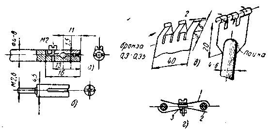
Figure 2 shows the designs of the circuit clamps for connection to the lamp. Figure 2c shows a springy flat clamp soldered into a groove in the line wires. The clamp is made from a 10 mm strip of sheet bronze (solid brass), at the end of the strip four or five cuts are cut with a jigsaw to a depth of 12 mm. The resulting strips are first bent in a vice into the grooved sides, and then, using a drill or a wire with a diameter of 1,5 mm, they are squeezed out, forming dense cylinders. The strips are elastic and provide reliable contact with the output of the GU-32 lamp. Contacts of this type can also be used for thinner leads, for example, for a 6NZP lamp. With a horizontal arrangement of the GU-32 lamp, it is desirable that the spring contact be a continuation of the line itself in the axial direction. This is most simply obtained if sockets from the socket for the GU-50 lamp are soldered into the line wire (Fig. 2, b). A reliable clamp can be made using a line conductor (Fig. 2, a). To do this, a longitudinal hole with a diameter of 1,5 mm to a depth of 11 mm is made from the end of the line and a through hole for the M2 bolt at a distance of 13 mm, then the wire is cut to a length of 16 mm and the upper part is separated. An M2 thread is made in the lower part, the cut planes are cleaned and both parts are again connected with an M2 screw. If the line is connected to the pins of the GU-32 anodes, then they can be firmly clamped by tightening the M2 screw. A shorting bridge for line adjustment can be made from a strip of bronze 0,3-0,4 mm thick, 10-12 mm wide, curved according to Fig. 2d. Through a central hole with a diameter of 3 mm and washer 3, strips 1 and 2 are tightened with an M3 screw and wrap around the wires of the lines. Designs of coaxial circuits The material for the structures are copper or brass tubes ranging from 4 to 100 mm. For such contours, hunting cartridges of caliber No. 12-32 are suitable. Their data are given in Table 1.
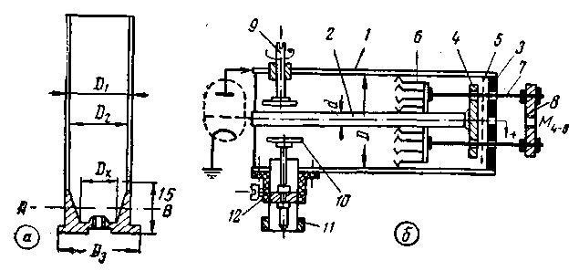
Sleeves no. 20/24 and 24/28 fit into each other with little play and can make sliding contact. The inner diameter of the sleeves approximately at a height of 15 mm from the bottom has a conical transition, so that in the bottom section the thickness of the sleeve increases from 0,5 to 2,0-2,5 mm, and this makes it possible to obtain any transitional diameters (Fig. 3, a ). Since the standard sleeve length is 70 mm, a quarter-wave circuit for 430 MHz can be made from two sleeves.
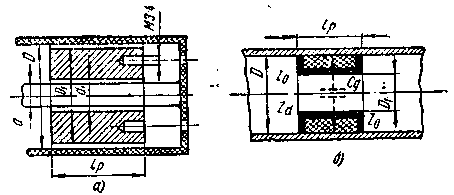
The surface of the materials used for coaxial circuits must be even, smooth and protected from rapid oxidation (silver, chrome). Figure 3b shows a simplified section of the coaxial circuit with the necessary working elements. Let us consider separately the purpose of these parts, their design and its options, in relation to amateur manufacturing capabilities. The diameters D and d of tubes 1 and 2 (Fig. 3, b) are determined either by the system of electrode leads for the lamps, or by the convenience of the design of the most critical element of the circuit - the tuning piston G. If the diameters of the tubes need to be changed slightly (by 1-2 mm) and by short distance, then solder the additional ring into the desired section of the tubes D and d
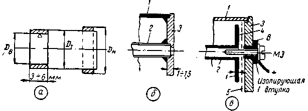
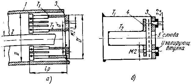
with subsequent processing to the desired diameter Dv and Dn (Fig. 4, a). Additional inserts are most often installed at the point where the lamp is connected to the line. In this case, soldered rings and a part of the carrier tube are cut along the generatrix in several places (6-12 strips or more) to obtain a springy contact. The length of the tubes is determined by the generator system and is discussed in the chapter on VHF transmitters. Coaxial circuits are usually short-circuited at one end, i.e., tubes 1 and 2 (Fig. 3b) are connected to each other using bottom 3 and disk 4 or without it (Fig. 4b and c). With non-separable connection of the tubes (Fig. 4, b), they are soldered into the bottom 3; for mutual precise centering, the bottom is made with recesses. If the bottom is not turned, then sufficient centering can be ensured as follows: on sheet metal, diameters D and d are applied with a sharp compass and the second diameters are 2 mm less than D and 2 mm more than d. These auxiliary circles help during manual processing to maintain the concentricity of the outer contour of the bottom and the inner hole with a diameter d, since during surface processing it is possible to control its curvature using the nearest auxiliary circles. Figure 4c shows the second option for connecting tubes 1 and 2 through a separating vessel. To do this, disk 2 is soldered perpendicularly to tube 4 and a thread is made at the end of the tube. The outer tube 1 is soldered into the bottom 3, in the center of which a bushing B of insulating material is passed. Tubes 1 and 2 are connected together with an M3 bolt, and mica 3 with a thickness of 4-5 mm is laid between the smooth, polished surfaces of the bottom 0,1 of disk 0,15: mica should reach diameter D. The diameter of disk 4 is made 2-3 mm less than D If the diameter of disk 4 is 30 mm, then with mica 0,1 mm thick, the capacitance of the isolation capacitor will be about 375 pF, and the capacitance of the transition at a frequency of 430 MHz is about 0,8 ohm. Such capacitors are necessary to separate RF circuits from power circuits. When connecting parts on VHF and microwave, it is very important to approach the soldering of parts very seriously. Poor soldering can degrade the quality factor of the circuits by two to three times. The most complex element of coaxial designs are tuning systems in a wide range. Usually this is done by longitudinal movement of the "short circuit", made in the form of different pistons. The essence of such a system is visible in Fig. 1-20,6, details 6, 7, 8. The main requirement for any restructuring system is the minimum losses introduced into the circuit by it, and their constancy over time. Since in amateur radio conditions it is possible to do without wide-range tuning, the system for rebuilding pistons sets out only the main considerations and piston designs that are most simply feasible; Contact petal piston, which produces a springy mechanical contact between the surfaces of the tubes of the coaxial circuit (Fig. 5, a);
- a sliding piston, creating a short circuit of the line through a significant capacitance (Fig. 5, b); - a dielectric piston, which gives frequency tuning due to a change in the wave resistance of the line itself (Fig. 6).
All other types of pistons - non-contact, z-throttle and others - are complex and difficult to repeat in amateur practice. The contact, petal piston (see Fig. 5) is easiest to assemble from pieces of brass tubes T1, T2 of suitable diameters with a wall thickness of 1-5 mm. Depending on the elasticity of the material and the possibility of processing, the length of the piston lp can be from 10 to 25 mm. The outer diameter of the T1 tube is reduced along the length by 0,4-0,5 mm so that a side 2-3 mm wide remains at one end. The same side is left for the T2 tube, but only on the inside. This allows the pressure to be concentrated at the ends of the tubes T1, T2 and significantly improves the reliability and consistency of contact. When machining on a lathe, a shallow (0,15-0,2 mm) groove can be made in the middle of the side, onto which a spring ring made of steel wire with a diameter of 0,4-0,6 mm is pulled during assembly. For tube T1, a groove is made from the inside, for T2 - from the outside (shown in dots in Fig. 5). Along the rim of the tubes, from the side of the side, longitudinal slots are machined with a jigsaw or a thin slot, creating contact petals. Their number and dimensions depend on the elastic properties of the material, the diameter and length of the piston. Typically, the petal width is about 2-3 mm on T2 and 3-5 mm on the outer tube. This operation must be done very carefully so as not to create permanent deformation in future petals, not to leave burrs and not to scratch the surface of the sides, which should always remain very smooth, sliding. Tubes T1 and T2 during this operation are put on wooden blanks of the required diameters. Then they are connected to the bottom 3 and soldered well. At the bottom, on a circle with a diameter of (D'+d'')/2, two or three holes are made with M2 or M3 threads for attaching rods 7 (see Fig. 2,b) necessary to move the piston. 8mm spokes can be a good material for pulls. Ring 4, which fastens the rods outside the system, has a central hole with an M6 or M4 thread, through which an M6 (M1) screw is passed, which creates a translational movement of the piston during rotation. Without such a kinematic drive system, it is impossible to tune in to the desired frequency "by hand". As tubes T2, T2 for the piston, it is sometimes possible to use the bases of hunting cartridges. The outer rim on the sleeve must be turned to the desired diameter. The side and the desired inner diameter of the T3 tube can be obtained by cutting off the rear part of the sleeve at a certain height (see Fig. XNUMX, a, cut lines AB). The contact piston creates a short circuit in the coaxial circuit both mechanically and electrically. Often, however, it is required that the high frequency circuit be closed, but there would be no short circuit in the general circuit for the power supply. In such cases, the piston must work as a container for RF currents and, therefore, the outer tubes T1 and T2 in it must be isolated from each other and at the same time have sufficient capacity. Such a design of a piston with a separating vessel is shown schematically in Fig. 5b. The piston is not much different from the design shown in Fig. 4c. Since the central part in the piston must be free for the passage of the inner conductor d of the coaxial circuit, the bottom 3 and the additional disk 4 soldered onto the piston tube T2 must be connected by three bolts located along the diameter T1 + T2 and be isolated from each other. This is achieved by a mica gasket (0,08-0,1 mm) and three bushings made of insulating material (plexiglass, ebonite). After assembling the assembly, it is necessary to check the insulation under high voltage (250-300 V). Short pistons have the advantage of a large range overlap, but they introduce significant losses, since the contact lobes are close to the antinode of the current always located in the resonator at the short-circuited end. To reduce losses, all surfaces must be smooth, the pressure of the petals is firm enough, but with a smooth ride. Chrome plating or nickel plating of the piston petals justifies itself well. The sliding piston is an aluminum cylinder that easily slides along the contour, the surface of which is anodized. The sliding cylinder is, as it were, the centering system of the contour. The dielectric piston, like the sliding piston, fills a part of the space inside the resonator and in this section reduces the wave impedance Zo of the line by the root of the "epsilon" times, i.e.
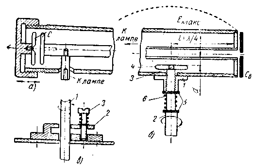
where e is the dielectric constant of the material; Zd and Zo are in ohms. The formula is accurate under the assumption that the dielectric fills the space without an additional air gap, in fact, the decrease in Zo is less than the calculated one. In the presence of a piston, the contour line becomes non-uniform with resistances Zo-Zd-Zo (see Fig. 6,b), which is equivalent to introducing some additional capacitance Cg in the place of the piston and, consequently, lowering the operating frequency. When the piston is moved from the short-circuited end of the circuit to the open end (toward the lamp) in a quarter-wave circuit, the frequency decreases linearly by an amount depending on e material and manufacturing accuracy (air gap). For a Mikanex piston (e = 7-9) 25 mm long at frequencies from 200 to 700 MHz, the change in the tuning frequency is 30-40%, while the losses increase rapidly in the region of the lowest frequencies. This is due to the fact that the piston is at the antinode of the voltage near the lamp, and the losses in the dielectric are proportional to the square of the voltage. This disadvantage is insignificant for operation in narrow frequency ranges, and the advantage of the dielectric piston is the absence of metal rubbing contacts. Unfortunately, the choice of suitable materials - heat-resistant, with large e and easily processed - is limited (micanex, ceramic). The range overlap that the described pistons give cannot always be used, since the widest range of 430-440 MHz requires a relative tuning in fmax - fmin \u1,06d 10, i.e. less than 3%. Under these conditions, the simplest is to adjust the lumped temporary capacity. One of the possible options for such a setting is schematically shown in Fig. 9b, detail 7, the other two - in Fig. 3. In all cases, a variable additional capacitance is introduced into the circuit at the place of a small RF voltage (according to Figs. 7 and 7, a at the end of the resonator), in the case of the design according to Fig. 3, b, at a distance from the short-circuited end. This case assumes that the total length of the resonator is 4/XNUMX lambda and the lamp is on at the open end.
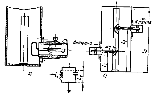
The adjustment is carried out by changing the distance between the additional disk and the central conductor of the coaxial system or, if a large adjustment is necessary, between two disks (Fig. 7, a). Sometimes for tuning in the range (usually at frequencies above 1 MHz), it is enough to introduce only the end part of the screw into the cavity of the resonator, for example, Mb or M000. The simplest design is shown in Fig. 7b. The nut (M4, M6) is securely fastened to the outer surface of the circuit. The screw 2 has an additional thread 3 at the end, on which the capacitor disk 4 is screwed in from the outside. Before assembly, a washer 2 is put on the screw 5, then an expanding spring 6 that eliminates backlash, and again washer 5. Since usually only one or two turns of the screw have to be used, a well-fitting spring does not introduce mechanical complications into the setting. The simplest connection of a coaxial circuit with a load or antenna is through a capacitance (see Fig. 3, b details 10, 11), in which the connection element - a pin with a disk - is located in the antinode of the voltage. The degree of connection is regulated by the movement of this element in relation to the middle conductor. In a simpler case, a coaxial connector with a coupling element is passed through the sleeve 12, which is rigidly fastened on the outside with a loop conductor. The required degree of connection is then fixed with a screw passing through the sleeve 12. The second characteristic method of communication - through the magnetic field of the resonator - is carried out using an inductive communication loop, always located at the short-circuited end of the line (Fig. 8).
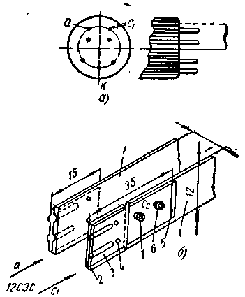
The degree of connection can be changed abruptly by changing the dimensions of the loop and the degree of connection by rotating the plane of the loop by 90°. You can fix the desired degree of connection with a locking screw (Fig. 8, a). Figure 8b shows the autotransformer connection of the antenna circuit using a common segment of the coaxial line l1 and the grid circuit using a long line l2. This helps to select the most favorable operating conditions (for example, in the input circuit of the receiver). True, such a selection for a coaxial design is difficult and is done for a prototype through a longitudinal slot in the outer cylinder. The tap position for a certain resistance transformation ratio K depends on the total length lo of the resonator itself. If the length lо is equal to a pure quarter wave (ideal case), then K=10 is obtained when the tap is placed at a distance l2=0,215L/4. If the total length lo is equal to 0,5L / 4 (a strongly shortened line), then when retracting l2 \u0,15d 4L / 10 K is XNUMX, etc. Connection of the lamp with high-frequency circuits The previous sections dealt with the operating conditions of RF circuits not connected to the lamp, or when this connection was purely schematic. In fact, on VHF, the mutual connection between these links is very strong: the lamp introduces into the circuit not only inhomogeneity, capacitance, but also significant losses. On the other hand, the highest efficiency of the lamp depends both on the magnitude of the resonant resistance of the circuit and on the phase of the voltage that external circuits create on the electrodes. The higher the operating frequency, the more critical these connections are. It has already been mentioned above about the influence on the outer contour of the inhomogeneity, which is the connected lamp. An important link in the design of VHF equipment is the transition, or the way the lamp is connected to the rest of the circuit. It is necessary that this transition does not introduce large reactances and losses into the external circuit. For special VHF lamps, for example, "beacon", this transition is already set by the concentric design of the conclusions themselves in relation to coaxial circuits. But in the ranges of 144 and 430 MHz, it is often necessary to use lamps of the usual finger series with pin leads. The use of a lamp socket lengthens these leads and introduces significant heterogeneity, especially noticeable at 430 MHz and higher. At these frequencies, it is better to do without panels, connecting the lamp directly to the circuit with some kind of clamp. In many VHF nodes, a coupling capacitor and grid leakage resistance are found. The operation of such circuits often depends on their implementation, and not on the value of the capacitance. If, in place of the isolation capacitor, a ceramic capacitor (of the KDK or KTK type) is taken into the grid circuit and connected to the lamp grid through the socket, then in the range of 430-440 MHz, the external inductance will have a length of 50-60 mm. Since L / 4 is approximately 17,5 cm, due to the capacitance of the lamp and the resulting inhomogeneity, the effective line length is only one third of the possible length, and this leads to a sharp decrease in the quality factor of the circuit and an increase in feedback and operating voltage. The design of an isolation capacitor Cc for a 12C3C (LD1) lamp is shown in Fig. 9. The lamp has two rigid outputs of both the grid and the anode (Fig. 9, a) and therefore it is convenient to make the contour between them in the form of a flat line from a strip of copper 10-12 mm wide and 0,8-1,0 mm thick (detail 1 in Fig. 9b).
At the ends of the strips, two grooves 2 0,5 mm deep are made and a strip 3 of bronze 0,3-0,35 mm thick is applied over them, in which two grooves are also squeezed out, and fixed on the line with two thin rivets 4. After that, the 12C3C lamp can be placed from the end side into the resulting socket clips. The end part of the line, to which the lamp grid is connected, is cut off at a distance of 15 mm and then attached to the line again, but through a mica gasket 5. This connection is easier to make using two two-millimeter screws 6 through insulating washers 7. Thus, a capacitor Cc with a capacity of 1-3 pF is formed between the strips 60 and 80, and at the same time an elastic system of clamps is used to connect the lamp. The uniformity of the contour line is not disturbed. As a result, the length of the outer line is 125-130 mm, i.e., shortening compared to L / 4 by only 40-50 mm. It turns out such a quality factor of the circuit that the generator, assembled at 430 MHz, works stably at a voltage of 10-15 V. The lamp, in addition to introducing a large intrinsic capacity into the circuit, also introduces significant attenuation. Measurements show that in the range of 400-700 MHz for a high-quality coaxial circuit (diameter 70 mm, length 370 mm) with a lamp of the GI11B type, the total relative losses in percentage are distributed as follows:
Consequently, more than half of all losses are created by the lamp, then there are losses from the contact piston (or the place of a short circuit-solder) and, finally, losses determined by the state of the cylindrical surfaces of the circuit. Different types of lamps shunt the external oscillatory circuit in different ways, lowering its resonant impedance even before the entire system (for example, a VHF generator) is loaded to full load. This effect can be paralyzed by creating higher-quality RF circuits with such a resonant impedance that, after all loads, it still provides the optimal load resistance Ropt with a sufficient margin for a generator lamp, as well as by connecting the lamp itself only to a part of the RF circuit using an autotransformer circuit. Literature:
Publication: N. Bolshakov, rf.atnn.ru
Artificial leather for touch emulation
15.04.2024 Petgugu Global cat litter
15.04.2024 The attractiveness of caring men
14.04.2024
▪ Hyundai S-A1 electric air taxi ▪ New 18W and 25W Network Adapters ▪ Human stomach grown in vitro ▪ New Series of Thick Film Power Resistors
▪ site section Acoustic systems. Article selection ▪ article Formwork with a clamp. Tips for the home master ▪ article What is slate? Detailed answer ▪ article Achokhcha cucumber. Legends, cultivation, methods of application ▪ article Non-contact phase indicator. Encyclopedia of radio electronics and electrical engineering ▪ article FM receiver at 144 MHz. Encyclopedia of radio electronics and electrical engineering
Home page | Library | Articles | Website map | Site Reviews www.diagram.com.ua |


 Arabic
 Bengali
 Chinese
 English
 French
 German
 Hebrew
 Hindi
Hindi Italian
 Japanese
 Korean
 Malay
Malay Polish
 Portuguese
 Spanish
 Turkish
 Ukrainian
 Vietnamese

 Leave your comment on this article: