|
|


 Arabic
 Bengali
 Chinese
 English
 French
 German
 Hebrew
 Hindi
Hindi Italian
 Japanese
 Korean
 Malay
Malay Polish
 Portuguese
 Spanish
 Turkish
 Ukrainian
 Vietnamese
|
ENCYCLOPEDIA OF RADIO ELECTRONICS AND ELECTRICAL ENGINEERING High quality IF audio amplifier. Encyclopedia of radio electronics and electrical engineering
Encyclopedia of radio electronics and electrical engineering / Телевидение To receive sound, currently produced televisions are built according to the so-called single-channel scheme. In them, the oscillations of the intermediate carrier frequency of the image (38 MHz) are used as heterodyne to extract the signal of the second intermediate frequency of the sound (6,5 MHz). With this design of the path, the frequency response of the IF image amplifier (IPHA) is usually optimal for the image signal, not the sound. Because of this, the quality of the audio signal is sometimes poor. In addition, when the image signal fails, it is also impossible to receive sound. However, there is another way to build radio paths of TVs - two-channel. In addition to UPCHI, in this case they contain an amplifier of the first IF (31,5 MHz) of the sound accompaniment (UPCHZ). At the same frequency, the received frequency-modulated signal is detected (without conversion to the second intermediate). Separation of image and sound channels allows you to design them optimally, eliminate mutual influence, and, consequently, improve the quality of sound. In addition, when using an all-wave selector on the TV, for example, SK-V-1, it becomes possible to receive broadcast programs on VHF, and when a stereo decoder is connected and the pre-distortion correction circuit is turned off, stereo transmissions become possible. Moreover, if necessary, the control voltage for the automatic local oscillator frequency control device (APCG) can be removed from the UPCHZ, and the device itself can operate at lower input signal levels than with single-channel reception. Main Specifications Real sensitivity at a signal-to-noise ratio of 26 dB, measured with a pre-distortion correction circuit at a frequency deviation of ±15 kHz and a modulation frequency of 1 kHz, μV .... 20 A schematic diagram of the UPCHZ, proposed for two-channel reception, is shown in fig. one.
The intermediate frequency signal of 31,5 MHz is amplified and limited in stages made according to the cascode circuit on transistors VT1-VT4, and in the DA1 chip. The use of cascode amplifiers based on field and bipolar transistors made it possible to obtain the required high and stable gain. Although the K174URZ (DA1) microcircuit is designed to operate at an intermediate frequency of 10,7 MHz, it turned out to retain satisfactory characteristics even when operating at a frequency of 31.5 MHz. Frequency selection in UPCHZ is provided by two-loop bandpass filters L1С6L2C7 and L4C13L5C14L6. UPCHZ bandwidth at -6 dB - about 600 kHz. For automatic frequency tuning (AFC) and the phase-shifting circuit of the detector of the DA1 microcircuit, a varicap matrix VD1 is included. When the signal frequency changes within the passband of the UPCHZ, the L7C23C24VD1 circuit adjusts so that detection occurs on the central, most linear section of the S-curve. This ensures minimal non-linear distortion. In addition, the local oscillator tuning bandwidth of the TV, which provides good picture and sound quality, is expanded. The 3H preamplifier is assembled on transistors VT5 and VT6. The AFC voltage to the channel selector can be removed from pin 8 or 10 of the DA1 chip, depending on the required polarity of the control signal. Coils L1, L2, L4, L5, L7 are wound with PEV-1 0,38 wire on polystyrene frames with a diameter of 5 and a length of 10 mm. The first four of them contain 11, the last - 14 turns. Coil 1.6 (2 turns of wire PEV-1 0,1) is wound between turns of coil L5. All coils are equipped with trimmers with a diameter of 4 and a length of 8 mm made of 9VN ferrite and are enclosed in screens soldered to the foil on the part side. To ensure communication between the coils L1, L2 and L4 - L6, holes were made in the adjacent walls of their screens (Fig. 2). The inductor L3 is wound on an MLT resistor (1 kOhm, 0.25 W) with a PEV-1 0,1 wire and contains 60 turns. The amplifier uses MLT resistors, capacitors K50-6 (K50-16), K10-7V and KD.
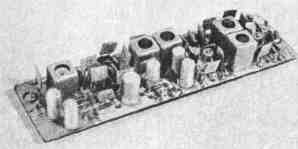
UPCHZ is mounted on a board made of double-sided foil fiberglass with a thickness of 1,5 mm. The drawing of the board and the placement of parts on it are shown in fig. 3, the appearance of the assembled device - in fig. four. The foil on the part installation side is connected to the common wire of the board, for which the leads of the parts connected to the common wire are soldered to the foil on both sides (holes for other leads are countersunk on the part side). It is desirable to place the board in a metal screen.
When adjusting, the currents through the transistors of the cascode amplifiers are set equal to 4 ... 6 mA by selecting resistors R2 and R8. To adjust the UPCHZ, you will need a frequency response meter. e.g. X1-48. First, before installing coils L4 - L6, pins 13 and 12 of the DA1 chip are connected through a 75 ohm resistor. The output signal X13-0,01 is fed to pin 1 through a 48 μF capacitor, and its low-frequency input is connected to the output of the UPCHZ. By rotating the trimmer of the L7 coil, they ensure that the middle of the S-curve coincides with a frequency of 31,5 MHz. Then, having replaced the coils L4-L6, they send a signal from X1-48 to the input of the UPCHZ, the detector head of the device is connected to pin 13 of the DA1 microcircuit and, by changing the inductance of the coils L1, L2 and L4-L6, they achieve maximum gain at a frequency of 31,5 MHz. The UPCHZ is finally tuned by applying a signal from a frequency-modulated signal generator, for example G4-70. Authors: V. Bogdanov, V. Pavlov; Publication: N. Bolshakov, rf.atnn.ru
Alcohol content of warm beer
07.05.2024 Major risk factor for gambling addiction
07.05.2024 Traffic noise delays the growth of chicks
06.05.2024
▪ The Ultimate Weapon Against Insects ▪ Under the gaze of the machine ▪ GPS alternative works even underground
▪ site section Electric meters. Article selection ▪ article Protect the pipe from birds. Tips for the home master ▪ article Who made the first clock? Detailed answer ▪ article Running in and testing of repaired machines. Standard instruction on labor protection ▪ article Fixatories for hair. Simple recipes and tips ▪ article Riddles about the house, buildings, furniture
Home page | Library | Articles | Website map | Site Reviews
www.diagram.com.ua |


 Leave your comment on this article: