|
|


 Arabic
 Bengali
 Chinese
 English
 French
 German
 Hebrew
 Hindi
Hindi Italian
 Japanese
 Korean
 Malay
Malay Polish
 Portuguese
 Spanish
 Turkish
 Ukrainian
 Vietnamese
|
ENCYCLOPEDIA OF RADIO ELECTRONICS AND ELECTRICAL ENGINEERING VHF transverter. Encyclopedia of radio electronics and electrical engineering
Encyclopedia of radio electronics and electrical engineering / Civil radio communications The described transverter set-top box, together with a transceiver having a 28 MHz band, provides communications in the 144 MHz band. The output power of the set-top box is 5 W, the nominal input power is 0,1 mW. The noise figure of the receiving path does not exceed 5 dB. The intermodulation dynamic range is no worse than 83 dB (when measuring the parameters of the receiving part, the set-top box worked in conjunction with a KB transceiver with a sensitivity of 1 μV and an intermodulation dynamic range of 90 dB.) The schematic diagram of the attachment is shown in fig. one.
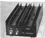
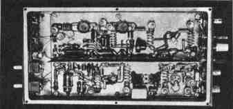
In the receive mode, the signal from the antenna is through the C1C3 divider, which allows you to select the optimal connection in terms of minimizing the noise figure. enters the input circuit L1C1C3. An RF amplifier is assembled on a transistor VT1, connected according to a common-source circuit. The use of a powerful field-effect transistor KP902A made it possible to obtain a high (approximately 10) and stable gain without neutralizing the through capacitance. The amplified signal is fed to a balanced mixer on VD3-VD6 diodes, where it is mixed with the local oscillator voltage. The local oscillator of the transverter is two-stage, on transistors VT2, VT3. The ZQ1 quartz resonator operates on the third (if quartz is used at a frequency of 12,888 MHz) or the fifth (quartz at 11,6 MHz) mechanical harmonic. The generation frequency within a small range can be changed by selecting a capacitor C11. The L5C12 circuit is tuned to 116 MHz. Transistor VT3 amplifies the local oscillator voltage to 7 V. In transmit mode, the signal from the transceiver goes to the same ring diode mixer, i.e. this part of the transverter is reversible. The converted signal with a frequency of 144 MHz is allocated by the L2C5 circuit. In order not to shunt the circuit with a small output resistance of the transistor VT1, a pin diode VD1 is installed, which is closed during transmission. In the receive mode, it is open to direct current and practically does not reduce the transmission coefficient of the RF amplifier of the receiving part. The output amplifier is four-stage, based on VT4-VT7 transistors. The first three transistors operate in class A mode, the last - in AB mode. The quiescent current of the transistor VT7 is stabilized by the VD8 diode and remains constant when the ambient temperature changes over a wide range. Elements C36, C38, R21 prevent self-excitation of the transmission path at infra-low frequencies. On transistors VT8-VT12 and LEDs VD10-VD14, a peak analog-discrete indicator of the output power is assembled. The signal from the collector of the transistor VT8 can be fed into the ALC KB system of the transceiver. The threshold for its operation is set by a tuned resistor R23, achieving a minimum of signal distortion in the transmission path. Transverter attachment (excluding power indicator) assembled on a printed circuit board (Fig. 2) from one-sided foil fiberglass with dimensions of 155X90 mm, which is mounted on an aluminum plate of the same dimensions with a thickness of 4 ... 5 mm, using stand-columns 5 mm high. The plate acts as a heat sink. All parts are placed on the board from the side of the foil. For ease of installation, it is desirable to install rivet caps in all holes. At the points where the wires and leads of the Ti and T2 transformers are soldered, it is advisable to install mounting pins or press pieces of tinned copper wire with a diameter of 0,8 ... 1 mm. The receiving part and the local oscillator are separated from the transmitting path by a 25 mm high partition made of brass or tinplate. A hole with a diameter of 2 mm is pre-drilled in it to output the capacitor C6. The appearance of the console is shown in fig. 3, internal - in fig. four.
Transistors KT368A can be replaced with KT355A, KT399A; KT610A - on KT610B, KT913A; KP902A - on KP905A; KT922A - on KT920A, KT925A. Instead of KD514A diodes, you can use AA112, AA120 or other diodes with a Schottky barrier. All these replacements slightly improve the performance of the structure. Instead of the KA507A diode, any pin diode with a lower capacitance than it or (with some deterioration in the gain) KD522A is applicable. Blocking capacitors (KM or K10-23) can have a capacitance ranging from 1000 pF to 0,33 uF. Transition capacitors must have the capacity indicated in the diagram. Instead of trimmer capacitors KT4-21, KT4-25 with a capacity of 6 ... 25 or 8 ... 30 pF is applicable. The winding data of the coils are shown in the table. All coils are frameless, made with a silver-plated wire with a diameter of 0,8 mm on a mandrel with a diameter of 5 mm. Chokes L3. L6, L9, L11, L16 - DM-0,4 with an inductance of 20 μH; L4, L7-DM-3 at 1 μH; L17, L19 - DM-2,4 at 12 μH. Chokes L7 and L4 can be replaced with homemade ones. They are made on a resistor MLT-0,25 with a resistance of 100 kOhm, turn to turn, winding the PEV-2 0,1 wire until the "frame" is filled.
The L15 inductor contains 5 turns of PELSHO 0,3 wire placed on the MLT-0,5 resistor with a resistance of 100 ohms. Transformers T1 and T2 are made on ring (size K7X4X1.5) magnetic cores made of 1000NN ferrite. Each of the windings contains 5 turns of PELSHO 0,23 wire. The winding is carried out in three wires. Without degrading the parameters of the transverter, ferrite rings (with a magnetic permeability of at least 50) closest to the specified size are applicable. Relay K1 (from the RES49 series) can not be installed, however, when working with an external antenna relay, which has a large capacitance between the contacts, or when using an additional power amplifier, the transmitting path may self-excite. It should be noted that the local oscillator of the attachment works stably with quartz, which is well excited by mechanical harmonics. On the case of such quartz resonators, their third, fifth or seventh harmonic is usually indicated. Therefore, it is desirable to use resonators at a frequency of 116,58 or 38,666 MHz. Modern quartz in miniature metal or glass cases, designed to operate at the fundamental frequency, in this transverter, as a rule, is also easily excited at the third and fifth harmonics. The establishment of a transverter set-top box begins with the tuning of the local oscillator. First, by removing the quartz resonator, a constant voltage of 12 V is set on the collector of the transistor VT3 with resistor R17. Then the resonator is connected and the frequency of the local oscillator is determined by a frequency meter or a KB receiver with a measuring attachment described in [L]. If there is no generation or the frequency is different from 116 MHz, it is necessary to select the capacitor C11 by installing a trimmer instead. In this case, it should be taken into account that the frequency of generation of a quartz resonator at the third and higher mechanical harmonics may differ by several tens of kilohertz from the calculated one, which is determined by the design of the quartz itself. After starting the crystal oscillator, the L116C8 and L21C5 circuits are tuned to resonance at a frequency of 12 MHz. At the same time, on the right terminal of the resistor R4 according to the diagram, the alternating voltage must be at least 5 V. The adjustment of the receiving part consists in setting a voltage of 1 V at the drain of the transistor VT16 and tuning the circuits L1C1C3 and L2C5 to resonance. If a radio amateur has a noise generator at his disposal, then it is advisable to use capacitors C1, C3 to select the optimal connection between the antenna and the circuit. Before establishing the transmission path, the equivalent of an antenna with a resistance of 75 ohms is connected to the output of the transverter. Then, resistor R13 sets a voltage of 6 V on the collector of the transistor VT4, R15 - 10 V on the VT5 collector, R19 - 17,5 V on the VT6 collector. Next, check the quiescent current of the transistor VT7. If it is outside the range of 5...20 mA. it is necessary to select the diode VD8. After that, instead of the KB transceiver, a standard signal generator (G4-18) is connected to the set-top box and a signal with a frequency of 28,5 MHz and a level of 0,1 V is supplied from it. from the input, all circuits in resonance. This operation is repeated several times. The voltage at the output of the transmitting path must be at least 20 V. If a lamp is used at the KB output of the transceiver with which the set-top box works, then it is necessary to install an anode voltage switch for the output stage. Literature
Author: A. Parnas (UB5QGN) Zaporozhye, Radio No. 11, 1988; Publication: N. Bolshakov, rf.atnn.ru
A New Way to Control and Manipulate Optical Signals
05.05.2024 Primium Seneca keyboard
05.05.2024 The world's tallest astronomical observatory opened
04.05.2024
▪ Baseus portable battery 180 mA ▪ Clothes with memory will adapt to the owner
▪ section of the site RF power amplifiers. Article selection ▪ article I'm going, I'm going, I don't whistle, but when I hit, I won't let go. Popular expression ▪ article From whom did Tibetans inherit genes that make life easier in the highlands? Detailed answer ▪ article Refueler of textile equipment. Standard instruction on labor protection
Home page | Library | Articles | Website map | Site Reviews
www.diagram.com.ua |


 Leave your comment on this article: