|
|


 Arabic
 Bengali
 Chinese
 English
 French
 German
 Hebrew
 Hindi
Hindi Italian
 Japanese
 Korean
 Malay
Malay Polish
 Portuguese
 Spanish
 Turkish
 Ukrainian
 Vietnamese
|
ENCYCLOPEDIA OF RADIO ELECTRONICS AND ELECTRICAL ENGINEERING Homemade low-resistance wire-wound resistor. Encyclopedia of radio electronics and electrical engineering
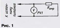
Encyclopedia of radio electronics and electrical engineering / Ham Radio Technologies In amateur radio practice, it often becomes necessary to make a wire resistor (or a pair of resistors) with a resistance of fractions or units of an ohm, and sometimes with fairly high accuracy. The task is complicated by the fact that conventional combined instruments - amperovoltmeters - manufactured by our industry are not applicable for measuring such small resistance values. Most radio amateurs cannot use specialized measuring bridges. The well-known "voltmeter method" is also of little use, since its implementation requires a set of low-resistance exemplary resistors, which is no less a problem. And yet such a resistor can be made. Any high resistance wire is suitable for this, for example, a spiral from an electric iron, electric stove or other electric heater. The larger the wire diameter, the easier it is to adjust the resistance of the manufactured resistor to a given value, but the larger the dimensions of the resistor will be. In this case, it is necessary to take into account the power that it must and can dissipate. First, a segment of the selected wire is separated of such a length that its resistance Rref is obviously greater than the required one. If the length of the segment is too long, it will be inconvenient to carry out subsequent operations with it. Connect as shown in Fig. 1, this piece of wire is connected to a powerful low-voltage voltage source and the voltage of the source Uist is measured with the possible accuracy with an avometer available to the radio amateur. It is desirable that at a voltage of Uist different 1 ... 2 V, the source without overload could provide a current of 5 ... 7 A. One section of an automobile or other battery can serve as such a source. A source of suitable quality will be obtained if, without disassembling its magnetic circuit, wind 180-200 turns of any insulated wire with a cross section of 3 ... Zmm4 on the coil of a transformer TS - 1,8 or TS - 2 in order to obtain a voltage of 0,9 ... 1,2 V.
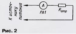
If the connected segment heats up quickly, up to a visible heat, then the current through it is too high, you need to take a longer segment. Measurements should be carried out as quickly as possible in order to minimize the additional error due to the thermal dependence of the resistance of metals. Of course, when using an alternating current source, measurements must be carried out with alternating current devices. Note that on alternating current, the resistance error of the manufactured resistor will be noticeably larger. Next, connect the same piece of wire to the same source as shown in Fig. 2, and the value of the current I in the circuit is measured with an avometer. Then the resistance of the segment Rotr \u4315d Uist / I - RoI, where RoI is the internal resistance of the avometer in the current measurement mode; the Rol value is easy to determine from the circuit diagram and the list of instrument elements for the used current measurement limit. For example, for the Ts2,5 device, with the switch position "1 A", the internal resistance can be taken equal to the shunt resistance RoI = R0,08 = 434 Ohm, and for the Ts0,045 device, the same value is XNUMX Ohm.
After that, it is necessary to measure the length L of the original piece of wire with a ruler. Then the length € of the part of this segment with the required resistance R can be determined as l = LR/Rref. A part of length l is cut off with a margin from both ends for tinning and soldering into the device (or for laying in clamps) so that there is a section of wire of length l between the soldering points. It can be wound around a suitable high-resistance resistor or, if the wire is thick, twisted into a spiral on a rigid mandrel. Example. It is necessary to make a wire resistor with a resistance of 0,25 Ohm (for a 3H power amplifier). A piece of wire of an electric iron spiral is connected to a source and a Ts4315 avometer, for example, measure the voltage, let Uist = 1,5 V. After that, measure the current I through the segment, I = 1,75 A. Then the resistance of the segment Rotr \u1,5d 1,75 / 0,08, 0,78 - 1,07 = 0,25 ohm. Suppose the length L of the piece of wire, measured with a ruler, turned out to be 1,07 m, then the length e for the resistance R = 0,25 Ohm will be l = 0,78x0,343 / XNUMX = XNUMX m. If the resistance Rotr turns out to be less, than R, this means that the segment was too short. Author: A.Terskov, Obninsk, Kaluga Region
Artificial leather for touch emulation
15.04.2024 Petgugu Global cat litter
15.04.2024 The attractiveness of caring men
14.04.2024
▪ Laser device that produces particles with negative mass ▪ NASA spacecraft was able to withstand an explosion on the Sun ▪ The hormone of love causes aggression ▪ Philips Tableaux E INK Digital Signage
▪ site section Electrical work. Article selection ▪ article Foreign literature of the XX century in brief. Part 1. Cheat sheet ▪ article How did discos appear? Detailed answer ▪ article Gorichnik nasturtium. Legends, cultivation, methods of application ▪ Dinistors article. Encyclopedia of radio electronics and electrical engineering
Home page | Library | Articles | Website map | Site Reviews
www.diagram.com.ua |

 Leave your comment on this article: