|
|


 Arabic
 Bengali
 Chinese
 English
 French
 German
 Hebrew
 Hindi
Hindi Italian
 Japanese
 Korean
 Malay
Malay Polish
 Portuguese
 Spanish
 Turkish
 Ukrainian
 Vietnamese
|
ENCYCLOPEDIA OF RADIO ELECTRONICS AND ELECTRICAL ENGINEERING Semi-automatic drilling machine with laser pointer. Encyclopedia of radio electronics and electrical engineering
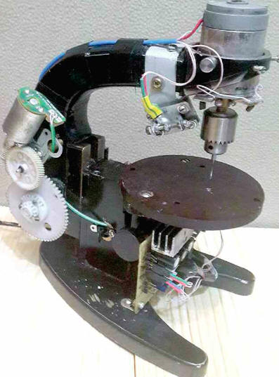
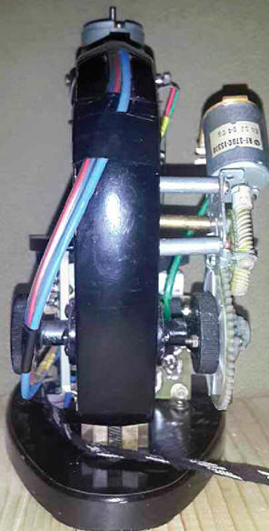
Encyclopedia of radio electronics and electrical engineering / Ham Radio Technologies To drill holes in printed circuit boards, many radio amateurs use the so-called microdrills, which are a miniature DC motor, on the shaft of which a drill collet is fixed. As a tool for processing printed circuit boards, microdrills are far from ideal: it is rather difficult to get into the exact center of the future hole without punching, and it is almost impossible to achieve the exact vertical position of the microdrill with your hands. The result is a low-quality "oblique" hole, the center of which is displaced on the other side of the board, or even a broken drill (it is especially easy to break an expensive carbide drill, which is made of a very fragile material). There are many options for drilling machines on the market, but they all have manual drill feed and significant backlash, and from electronic "software" they contain only a power supply and a speed stabilizer for the drive motor. The self-made drilling machine described in the article allows you to drill holes without prior punching. The logic of its work is controlled by a microcontroller. When working on this machine, expensive carbide drills do not break. Thanks to the use of such drills, the quality of the holes is improved - they literally cut a hole, so after drilling there is no need to process the foil with sandpaper, which makes the thin foil of printed conductors even thinner. I have drilled over 1500 holes on this machine with a single carbide drill (made in Germany) and it still hasn't broken and continues to drill high quality holes. A cheap drill usually stops drilling well after 10-20 holes in foil-coated fiberglass, so you have to increase the speed of the drill and increase the pressure when drilling, as a result, foil rolls form around the holes, and after drilling, thorough processing of the conductors with sandpaper is required. The machine (its appearance on the left, right and back is shown in Fig. 1-3, respectively) is made on the basis of the domestic microscope MBI-3 manufactured by the LOMO association. Its operation is controlled by the control unit (CU), the diagram of which is shown in Fig. 4. It is based on the ATtiny45 microcontroller [1]. When power is applied, the CU sets the machine to its original position, i.e. if its movable part was in the lower or intermediate position, then it automatically rises to the initial upper position. Next, the board to be processed is positioned under the laser beam (they make sure that the laser beam hits the center of the hole), they press it against the work table with their hand and press the pedal. At the same time, the control unit supplies power to the electric motor of the drill chuck drive and the drill feed motor. At the end of drilling, the drill feed motor returns the machine to its original state and the control unit turns off the power to both motors. The machine is ready to drill the next hole.
As a laser pointer, a modified laser module is used, which is used in children's toys. It is necessary to focus the laser collimator over a short distance and limit the supply current, which should be such that the laser is just starting to shine. This allows for a thinner beam (I was able to achieve a beam diameter of 0,2 mm) and reduces the laser radiation to a safe level. The assembled laser attachment unit is shown in fig. 5, and drawings of its details - in fig. 6. The base 3 and the laser holder 4 are made of about 1mm thick sheet steel (I used the case walls of an old CD-ROM). Having drilled the necessary holes in the blanks, the rectangular petals are bent at the holder 4 at a right angle for fastening the screw with the laser module. The module is disassembled, the soldering point of its brass body and two M3 nuts are tinned. Screw 4 (M5x3) is inserted into the holes of the bent petals of the holder 28 and both nuts 8 are screwed onto it so that they are between the lugs of the holder (see Fig. 5). Laser body 2 is inserted under screw 5 (between nuts 8) and the nuts are soldered to it so that it fits snugly against the holder (this is necessary for backlash-free movement of the laser when the screw is rotated during adjustment).
Next, two more nuts 5 are screwed onto the protruding end of the screw 1 (one of them will be a lock nut) and tightened so that the lugs of the holder 4 prevent the screw 5 from moving along the axis. Now, when the screw is rotated clockwise and in the opposite direction, the laser module will move from one lug to the other. To fasten the holder with the laser on base 3, four nuts are soldered to the latter on the reverse side (they are clearly visible in Fig. 2). Then, four screws 7 (M3x15) with washers 6 placed under the heads are inserted into the corresponding holes of the holder from the laser side, and cylindrical compression springs are put on them, after which they are screwed into the nuts soldered to the base. Now, with the help of screws, you can adjust the position of the laser in different directions. The assembled structure is tried on to the tube holder (upper part of the microscope), the shank of the laser holder base is bent around it and, transferring the contours of the holes in the base to the tube holder with a sharp scriber, two holes are drilled in it with a diameter of 2,5 and a depth of 10 mm and thread M3 is cut into them. Finally, fix the base of the laser holder on the microscope with M3 screws. To feed the drill, an electric motor with a worm gear from a VCR was used (I disassembled the device for a long time, so I can’t indicate its name). This mechanism (Fig. 7) is attached to the tube holder of the microscope using three metal posts with M4 internal and external threads and the same number of M4 screws. The gear is fixed on the handle of the microscope with three M2,5 screws with nuts, the holes in both parts are through. Care must be taken during assembly - misalignment of the gear and handle should be minimal.
The feed rate is regulated by a tuning resistor R11. The electric motor used is low-power (rated voltage - 6 V, current - 30 mA), but thanks to the worm gear, it copes with its task quite well. The design of the gearbox can be any, but must provide sufficient force to easily turn the handle of the microscope. You can use a stepper motor. In the first project, I did just that, but the existing stepper motor had insufficient torque on the shaft, and I could not find a suitable one. If anyone has an interest in using a stepper motor, you can contact me through the editors. The project files are saved. It used the ATmega8 microcontroller. The key on the composite transistor VT5VT6 turns on and off the drill feed motor (it is connected to the XP6 plug), the VT2 transistor and the K1 relay control its direction: up or down. The key on the VT3VT4 composite transistor controls the drill drive motor (it is connected to the XP3 plug), a frequency regulator for its rotation is assembled on the DA1 microcircuit and the VT1 transistor, and the frequency is adjusted with a tuning resistor R1. It makes no sense to use a more complex speed stabilizer, for example, as proposed in [2], since it is not necessary to “aim” with a drill at the center of the hole “by eye”. Experiments have been carried out on this matter. On the DA6 chip, a voltage regulator for the supply of the drill feed motor is assembled [3]. The integral stabilizers DA2 and DA5 connected in series are designed to obtain stabilized voltages of 12 and 5 V, respectively. Capacitors C3, C4, C2 - filtering, the rest - blocking. The machine has LED lighting. The backlight current and the laser current are stabilized: a laser current stabilizer is assembled on the DA3 chip, and the backlight LEDs are on the DA4. The stabilization current is calculated by the formula I = 1,25 / R [3] and is set by a selection of resistors R13 and R14. Due to the stabilized current, it is possible to connect several backlight LEDs of the same type in series. The laser is connected to the XP4 plug, the LEDs are connected to the XP5. The XP7 connector is designed to connect the programmer. The purpose of its contacts corresponds to the programmer "TRITON + V5.7T USB" [4]. The microcontroller program was developed in the Code VisionAVR V2.05 integrated environment [5, 6]. A two-position sensor of the extreme upper and lower positions of the drill and a drilling start button are connected to the XP2 connector. The latter is connected to pins 2 and 4, the upper position sensor - to pins 1 and 4, the lower one - to pins 3 and 4. The sensor and the button have normally open contacts, which, when triggered, close to a common wire. A limit switch mounted in the pedal is used as a button. The position sensor is used from the DVD player of the music center. The operation of the sensor in the lower position is adjusted so that the drill falls no more than 1 mm below the processed board. The upper position sensor regulates the maximum stroke of the drill; it makes no sense to make it more than 20 mm. The adjustment is made by moving the racks of elastic wire 3 (Fig. 8), fixed with screws 6 (M3) on the bracket 5. The screws are screwed into rectangular threaded plates through a slot in the bracket, which allows you to move the limiters up and down. Threaded plates, rather than standard nuts, are used in order to be able to fix the position of the posts in the found position without using any tool to keep the nuts from rotating while tightening the screws 6. You can solder the plates to the nuts. The bracket is fixed with screws 4 on the tube holder, and the sensor 2 - on the L-shaped bracket screwed to the base of the microscope. The drawing of bracket 5 is shown in fig. 9, it is made, like the parts of the laser holder, from sheet steel.
The power supply voltage of the machine depends on the drill drive motor used, but should not be lower than 14 V. I used a print head movement motor from a Canon inkjet printer with a nominal supply voltage of 24 V. The power supply voltage of the machine was selected with a margin of adjustment - 30 V. The current consumption is total devices in steady state (during drilling) - 1,5 A, at the time of starting the engines, it briefly increases to 3 A. Thus, the power supply must provide an output voltage of 30 V with a current consumption of at least 3 A. I use a home-made switching laboratory power supply with a linear stabilizer 0 ... 50 V, 0 ... 10A. Current limitation gives smooth start of motors. The details of the control unit are mounted on a printed circuit board made of one-sided foil fiberglass, made according to the drawing shown in fig. 10. The pattern of printed conductors is applied by exposing an image from a photo negative onto a workpiece foil coated with a photoresist. The negative photomask can be printed with an inkjet printer at maximum quality.
Fixed resistors R3, R7-R9, R15, ceramic capacitors C1, C4, C5, C7 (all sizes 0805 for surface mounting) and microcontroller DD1 (in SOIC8 package) are soldered directly to the printed conductors. The rest of the resistors are MLT-0,25, the capacitors are oxide imported. Transistors VT1, VT4, VT6 - any series KT805, KT819, VT3, VT5 - BC337, BC547, 2N2222, series KT315, KT3102; VT2 - ВС337, 2N2222, any of the series KT630, KT815, KT972 (the maximum value of its collector current must not be less than the operating current of relay K1). One KT5 or KT6 series transistor can be used as a VT829VT972 key, and one KT3 or KT4 transistor with any letter index can be used as a VT827VT829 key. Relay K1 - R40-11D2-5/6, it can be replaced by any other with a response voltage of 5 V and with two groups of switching contacts designed for switching current of at least 1 A. You can use a 12 V relay by connecting the upper (according to the diagram) output its windings (together with the VD1 diode) to the output (pin 3) of the DA2 chip. The control board is installed under the table and fixed with M3 screws through the corners to the microscope base (see Fig. 1). Chips DA2 and DA5 are installed on heat sinks. It is desirable to provide a heat sink and transistor VT1. The table is made of textolite. Before converting to a drilling machine, the microscope must be disassembled, thoroughly washed off with a rather viscous lubricant that impedes the movement of the tube holder (the upper part of the microscope), and lubricated with a liquid lubricant, for example, transformer oil. The movement of the upper part should be as easy, smooth and without play as possible. It was decided to abandon the use of a classic collet for fastening a drill. A Morse taper and a three-jaw chuck for drills with a diameter of 0,3-4,5 mm are used. The connection of the engine with the cartridge must be free of beats. Adjustment of the laser point on the board being processed using screws is carried out in the following order: a hole is drilled in a plate of foil fiberglass similar to that from which the board is made, then the laser point is adjusted exactly to the hole with the adjusting screws of the holder. In this case, you must try not to displace the plate. In my experience, if the laser dot disappears (stops reflecting off the foil), then the laser beam has entered the hole and is aligned. The thickness of the fiberglass should be the same as that of the manufactured board. After that, you can be sure that the laser will accurately indicate the center of the future hole. With serviceable parts and error-free installation, the control unit does not need to be adjusted. The machine has been in operation for over a year. During operation, both hands are free, and therefore it is convenient to work on the machine. I haven't broken a single drill, although I make boards quite often and I don't know how I got by without this machine before. Now I boldly buy high-quality expensive drills. Drilling 50 holes takes no more than half an hour. But still, care is needed, there is a danger of breaking a fragile drill when installing the board on the working table of the machine - inadvertently hitting the drill. The probability of breakage of the drill during drilling is small, unless, of course, you move the board at this time. The microcontroller program, as well as negative and positive photomasks in .pdf format for transferring the pattern of printed conductors to the printed circuit board blank, can be downloaded from ftp://ftp.radio.ru/pub/2015/07/stanok.zip. Literature
Author: I. Parshin
Artificial leather for touch emulation
15.04.2024 Petgugu Global cat litter
15.04.2024 The attractiveness of caring men
14.04.2024
▪ Plants to purify the air in space stations ▪ VHS continues to lose ground ▪ New series of SONY LCD monitors
▪ section of the site Electrical safety, fire safety. Article selection ▪ article And then an inventor appeared. Theory of inventive problem solving ▪ article What miracle did Jesus perform while still in the womb? Detailed answer ▪ article Signs of a change in inclement weather to clear. Travel Tips ▪ article Kettle automatic switch. Encyclopedia of radio electronics and electrical engineering
Home page | Library | Articles | Website map | Site Reviews
www.diagram.com.ua |


 Leave your comment on this article: