|
|


 Arabic
 Bengali
 Chinese
 English
 French
 German
 Hebrew
 Hindi
Hindi Italian
 Japanese
 Korean
 Malay
Malay Polish
 Portuguese
 Spanish
 Turkish
 Ukrainian
 Vietnamese
|
ENCYCLOPEDIA OF RADIO ELECTRONICS AND ELECTRICAL ENGINEERING Improvement of the soldering iron Moment. Encyclopedia of radio electronics and electrical engineering
Encyclopedia of radio electronics and electrical engineering / Ham Radio Technologies The author shares his experience of improving the Moment soldering iron. After a simple revision, which took only a few hours and required a dozen radio components, it became much more convenient to use. Many radio amateurs have such a soldering iron. Its feature is clear from the name - the sting heats up within a few seconds. And the greater the heating power, the less time it takes to reach the desired temperature. But when soldering, high power is no longer needed - the tip overheats, the rosin quickly burns and the soldering is of poor quality. You have to regulate the temperature by manipulating the power button: release it when the sting overheats and press it again when it cools down too much. With a certain dexterity, the soldering turns out to be quite good. It is clear that this is very inconvenient, and distracts from work, because you have to constantly monitor the temperature. Having purchased a Polish-made Moment soldering iron with a power of 100 W, I used it infrequently. Basically, when it was necessary to desolder or solder something once, but I didn’t want to wait for the usual soldering iron to warm up for one single soldering. Later, I began to turn on this soldering iron through an adjustable autotransformer built into the mounting table. The sting no longer overheated, but its heating was delayed up to several tens of seconds. However, it was still much faster than waiting for a regular soldering iron to heat up. And that's when I thought that I need to combine the rapid heating of the sting with the regulation of its temperature. Initially, I used a conventional switch for this, with which I connected the soldering iron first directly to the mains (for quick warm-up), and then through an autotransformer so that the tip would not overheat during soldering. The disadvantage of such a solution is obvious - every time, taking a soldering iron in hand, you need to reach for the switch installed quite far from it. Nevertheless, I used the soldering iron in this way for about a month, until I took this problem seriously. The idea was born to use a time relay so that after a few seconds of warming up, it switches the soldering iron to a lower voltage. Instead of a bulky adjustable autotransformer, it was planned to use a trinistor voltage regulator. I have already begun to select a case in order to mount a time relay with a voltage regulator in it. But in the process of this selection, weighing all the pros and cons of this idea, I came to the conclusion that the time relay is not the best option. Built according to a simple scheme, it will not provide stable endurance in conditions of fluctuating mains voltage, changing temperature and speed of the air surrounding the soldering iron. And I didn’t want to assemble a device that was too complicated at all. Based on this, I came to the conclusion that the radio amateur still has to switch the soldering iron from full mains voltage to low voltage at the very moment when he considers it necessary. But it is best to install the switch or button necessary for this on the soldering iron itself. And in order not to pull wires from this switch to the voltage regulator, you need to mount the regulator inside the soldering iron body. This will eliminate the need for a separate housing for the regulator. After all, there is always not enough space on the desktop of a radio amateur. To reduce the heating power, I used a well-known trinistor phase-pulse power controller, including it in the primary winding circuit of the Moment soldering iron transformer. The scheme of such a regulator is shown in fig. 1. Voltage is supplied to it when the XP1 plug is plugged into a power outlet. Since the control electrode of the trinistor VS1 is disconnected from the phase-shifting circuit by the open contacts SB1.2 of the button, the trinistor is closed, the current does not flow through the I winding of the transformer T1.
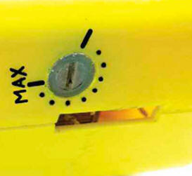
In this mode, the indicator LED HL1 lights up, signaling that the XP1 plug is connected to a socket in which there is voltage, and the power cord, winding I of the transformer T1 and inductor L1 are not interrupted. The LED should be red and bright enough to help you remember to unplug the XP1 from the socket when you're done. Contacts SB1.2 belong to the power button already in the soldering iron. They are transferred from the primary circuit of the transformer to the control electrode circuit of the trinistor VS1. And that's why. When opening the contacts located in the circuit with a large inductance of the primary winding of the transformer, a self-induction voltage pulse occurs, which causes sparking of the contacts, which leads to their premature wear. In our case, this pulse, the amplitude of which is much greater than the nominal mains voltage, would be applied to both the rectifier bridge diodes VD1 and the trinistor VS1, creating the risk of their breakdown. Additional contacts SB1.1 (microswitch MP3) are installed on the power button during revision. The microswitch is fixed with hot glue so that when the button is pressed, its contacts SB1.2 first close and only when pressed further, the microswitch contacts open. When the button is partially pressed, which caused only the closure of contacts SB1.2, the power regulator starts to work. Since the resistor R1.1 shunts the resistors R6 and R3 of the phase-shifting circuit through the remaining closed contacts SB5, the trinistor VS1 opens at the very beginning of each half-cycle of the mains voltage and almost the full mains voltage is supplied to the primary winding of the transformer. The soldering iron heats up quickly. In this mode, the voltage drop across the VS1 trinistor is minimal, so the HL1 LED does not light up, which indicates that the soldering iron is heating up. When the desired temperature is reached, press the button all the way. Contacts SB1.1 will open, resistor R6 will stop shunting resistors R3 and R5, so the SCR opening delay will increase. The heating power of the soldering iron will decrease. In this case, the HL1 LED and the EL1 soldering iron control lamp will light up with incomplete brightness. The transformer hums softly, as a distorted voltage is supplied to it. All this signals that the soldering iron is operating at reduced power, depending on the position of the trimmer resistor R3. Pressing the soldering iron on button so that the SB1.2 contacts open and the SB1.1 contacts remain closed is not easy, training and care are needed. But this is facilitated by the fact that during heating, the soldering iron is simply held in the hand, without being distracted by soldering. During soldering, you need to press the button all the way and hold it in this position, which is not difficult at all. That is why heating occurs when the button is pressed halfway, and soldering occurs when it is pressed all the way, and not vice versa. One-button operation of the soldering iron allows you to quickly increase the temperature of the tip, if necessary, by slightly releasing the button. When the need for this passes, the button is pressed all the way again and the temperature drops to the value set by the tuning resistor R3. There is no need to adjust this regulator as carefully as described in my article "Improving the device for burning out" ("Radio", 2014, No. 9, pp. 44, 45). The only thing is to select the resistance of the resistor R5 so that when the trimming resistor R3 is fully inserted, the solder barely melts, and when the tip temperature is fully withdrawn, it is sufficient for normal soldering. Since the regulator is built into the body of the soldering iron, the parts used must be small. The trinistor PCR606 is taken from a serviceable switching unit from a Chinese garland, the lamps of which have burned out. Naturally, different SCRs can be installed in different blocks (usually PCR406, PCR606, PCR806), but their parameters are very close, so any serviceable one will do. I recommend replacing the RC207 rectifier bridge with a bridge of the same round shape, for example, 2W10M, BR810. Such bridges are small in size and are ideal for surface mounting. They have pretty hard conclusions. If you bend the leads in different directions, it is convenient to solder the rest of the device on them. Of course, other rectifier bridges are also suitable, with a permissible reverse voltage of at least 600 V and a rectified current of at least 300 mA. The DB3 symmetrical dynistor was taken from the ballast of a faulty energy-saving lamp. It can be replaced with DB4 or, if space permits, with the domestic KN102A dinistor, of course, observing the polarity of its connection. Capacitor C1 is taken from the same ballast. Instead of the MP3 microswitch, you can use another one that is suitable in size. As R3, I used a tuning resistor SP3-1b, drilling a hole with a diameter of 8,1 mm in the body of the soldering iron for its round rotating part with a slot. The resistor itself was glued with hot glue on the inside of the case. As a result, it turned out very convenient (Fig. 2) - nothing sticks out, does not interfere, and it is very easy to adjust the tip temperature even during soldering.
Inductor L1 contains five layers of varnished wire with a diameter of 0,6 ... 0,7 mm, neatly wound coil to coil on a ferrite rod with a diameter of 8 ... 10 mm and a length of 2,5 ... 3 cm. You can place it in the handle soldering iron. It makes no sense to describe in detail the placement of the regulator in the body of the soldering iron. It depends on the design features of the soldering iron and the parts used. Explanations require only the installation of microswitch SB1.1 and LED HL1. Sometimes the design of the soldering iron is such that it is not possible to install the microswitch so that when the switch button is pressed, its contacts SB1.2 first close, and only then the contacts of the microswitch SB 1.1 open. In this case, to switch the mode of operation of the regulator, you will have to use a separate button or switch, setting it in a place convenient for pressing with a free (for example, thumb) finger. For the HL1 LED, I did not drill a hole. The body of my soldering iron is made of yellow plastic, through which the glow of this LED is perfectly visible. If the body of the soldering iron is opaque, drill a hole for the LED in such a place that it is clearly visible, but does not blind the eyes, interfering with work. A few words about the backlight (EL1 in Fig. 1). It burns out quite often, so it is advisable to replace it with a white LED. The brightness of the backlight will be even greater than with an incandescent lamp. Therefore, I recommend that when the backlight in your soldering iron burns out once again, replace it with an LED. It is very easy to do this. Wrap the burned-out lamp in paper and break off the glass bulb from the base with pliers. Clean the inner side surface of the base from the remnants of glass and glue with which the flask was glued. It is necessary to work very carefully so as not to cut yourself with glass fragments, and preferably in safety glasses so as not to injure your eyes with fragments. Solder one lead of the LED to the center pin and the other lead to the side of the base. The entire structure can be filled with some kind of glue for hardening, but this is not necessary at all. The LED can be taken of any type in a transparent case. The voltage of the winding III of the soldering iron transformer is only 2 ... 2,5 V. This is not enough to directly connect a white LED to it. Therefore, it is assembled according to the scheme shown in Fig. 3, voltage doubling rectifier.
Select the capacitance of capacitors C2 and C3 empirically by controlling the current of the LED. Install the 20uF capacitors first. With them, the current through the LED I got about 20 mA. If this is not enough, install larger capacitors. Select the current with the regulator on so that the brightness of the backlight is sufficient for soldering. Naturally, during warm-up, the brightness will be greater, but I consider it unnecessary to complicate the device by adding a current stabilizer, and there was simply no place for it. Diodes KD105B can be replaced by any small-sized rectifier diodes with a reverse voltage of at least 20 V and a permissible rectified current of at least 50 mA. For example, KD102A, KD103A or KD105 with a different letter index. The multiplier was assembled on a board made of foil fiberglass with dimensions of 30x12 mm. Its drawing is not shown due to its simplicity. If you use diodes KD102A or KD103A, then the dimensions of the multiplier board can be even smaller. You can place it in any free space in the case. For example, as shown in fig. 4. When connecting the board to the socket, consider the polarity of the manufactured LED lamp.
Author: A. Karpachev
Artificial leather for touch emulation
15.04.2024 Petgugu Global cat litter
15.04.2024 The attractiveness of caring men
14.04.2024
▪ Apple and Google have completely switched to renewable energy sources ▪ Plankton of the Black Sea rids the Earth of carbon ▪ The Pain Relieving Power of Music ▪ You need to quit smoking fast ▪ Application of Ara Modular Smartphone Components for Wearable Electronics
▪ section of the site Electrician in the house. Article selection ▪ article Yes - yes, no - no, what is more than that is from the evil one. Popular expression ▪ article Bank branch manager. Job description ▪ Time relay article. Encyclopedia of radio electronics and electrical engineering
Home page | Library | Articles | Website map | Site Reviews
www.diagram.com.ua |


 Leave your comment on this article: