|
|


 Arabic
 Bengali
 Chinese
 English
 French
 German
 Hebrew
 Hindi
Hindi Italian
 Japanese
 Korean
 Malay
Malay Polish
 Portuguese
 Spanish
 Turkish
 Ukrainian
 Vietnamese
|
ENCYCLOPEDIA OF RADIO ELECTRONICS AND ELECTRICAL ENGINEERING Liquid flow control relay. Encyclopedia of radio electronics and electrical engineering
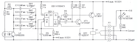
Encyclopedia of radio electronics and electrical engineering / Clocks, timers, relays, load switches The author of this article, by the nature of his work, had to control the flow of water that cools complex physical devices, for example, X-ray spectrometers. The sensors provided for this purpose turned out to be unreliable, requiring frequent maintenance, repair and replacement. All problems were solved with the help of a cheap household water meter, to which a simple (only one K155AGZ chip) electronic assembly was added. In water cooling systems for physical devices, liquid flow control relays RPZh-8 are used, which require frequent adjustment due to the loss of elasticity of the rubber membrane, as well as rotameters with reed switches that respond to the rotation of a float with a magnet. Both of them quickly become contaminated with tap water and need periodic cleaning to prevent failures in the alarm system for an emergency decrease in coolant flow. One day the idea came to try to install in the water cooling system a wing-type water meter SVK-15-3 that proved to be trouble-free in everyday life. I dismantled its counting mechanism, leaving only the upper and lower plates with the drive shaft and the "asterisk" mounted on it. The shaft has a magnetic connection with the impeller located in the water flow. On it, approximately in the middle, I planted a shutter made of plastic gear from a portable radio tape recorder, which blocks the optical connection between the emitting diode and the phototransistor of the optocoupler with an open optical channel (from a faulty printer). The damper shape is chosen such that there is no communication during half of each revolution of the shaft. The optocoupler is mounted on a fiberglass board placed between the plates of the counting mechanism, of course, without gears and a counter. The axle with damper and sprocket is installed in its sockets (bearings). The resulting sensor is mounted directly on the flow converter (manufacturer's terminology) of the meter and connected to the water supply. The optocoupler is connected according to a scheme similar to that used in the final version of the sensor (it will be discussed below). The pulse frequency at the phototransistor collector was measured from their image on the oscilloscope screen. A flow of a given intensity was created by pouring water into a measuring container. It turned out that the frequency of pulses generated by the sensor is directly proportional to the minute water flow. At 6 l/min it is equal to 3 Hz. It was decided to build a threshold device that generates a signal about an unacceptable decrease in water flow based on the principle of comparing the repetition period of the sensor pulses with the duration of the single vibrator pulses. Variants were tested on various microcircuits - KR1006VI1, KR1561AG1, K555AG1. Unexpectedly, the best and requiring the minimum number of parts turned out to be the version on the K155AGZ chip (two single vibrators with a restart). Its scheme is shown in Fig. one.
When the damper rotates, pulses are formed on the collector of the phototransistor of the optocoupler U1, the duration of which is approximately equal to the duration of the pauses between them, and the repetition rate depends on the water flow in the cooling system. Depending on which of the switches SA1-SA4 is closed, the pulses through one of the capacitors C1-C4 (their capacitance is selected experimentally) are fed to input 2 of the single vibrator DD1.1. With a low repetition rate, their amplitude is insufficient to start it and the voltage level at the output 4 of the single vibrator remains constantly high. Transistor VT2 is closed, and the contacts of relay K1 (RES42 version RS4.569.151) are open. With an increase in water flow, the speed of the sensor impeller and the repetition of pulses on the collector of the phototransistor increases. The amplitude of the pulses at the input of the single vibrator also increases. At a certain threshold value of the flow rate, these pulses begin to trigger the one-shot. Since the period of their repetition is less than the duration of the single vibrator pulse, the latter restarts multiple times and the level at its output becomes constantly low (this is typical for a single vibrator on the K155AGZ chip). Transistor VT3 opens, relay K1 is activated, its contacts close the circuit that allows the operation of the cooled device. The connection diagram of the signal LED HL1 to the X1 connector is given as an example. When the flow rate drops below the threshold, the relay contacts will open no earlier than after 6 s (univibrator pulse duration). This delay prevents false triggering of the signaling device in case of uneven water supply. As switches SA1-SA4, a block of DIP switches VDM-4, removed from the computer board, was used. Capacitors C1-C4 are selected experimentally by rotating the sensor shaft at the desired frequency with a low-power electric drive with adjustable speed. If necessary, capacitors of the required capacity are assembled from several connected in parallel. If one threshold value is sufficient, the switches can be omitted, leaving only one of the capacitors C1-C4 in the device.
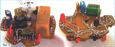
All parts of the signaling device are mounted on a printed circuit board, the shape of which corresponds to the free space inside the body of the measuring mechanism of the SVK-15-3 water meter. The top and bottom views are shown in fig. 2. The board is placed between the plates of the mechanism, a shaft with a damper and an asterisk for visual rotation control is installed. The free end of the shaft is inserted into the socket intended for it in the lower (black) cover of the meter. Install the top (transparent) cover until it snaps into place with the bottom. A slot is made in the transparent cover for controlling SA1-SA4 switches with a screwdriver. The assembled electronic unit is installed on the "flow converter" of the meter and fixed with a clamp. The unit can be easily removed for inspection, repair or replacement without having to remove the "flow converter" from the water supply. It is likely that the number of damper blades that interrupt the flow of IR radiation in the optocoupler U1 can be increased by increasing the frequency of the pulses generated by the optocoupler. This would significantly reduce the capacitance of the capacitors in the sensor. Unfortunately, I have not tested this possibility in practice. Author: A. Skorynin, Zlatoust, Chelyabinsk Region; Publication: radioradar.net
Machine for thinning flowers in gardens
02.05.2024 Advanced Infrared Microscope
02.05.2024 Air trap for insects
01.05.2024
▪ Economy hatchback Peugeot 208 ▪ New microcontrollers for electronic lamp ballasts ▪ Tesla will release an amphibious electric car
▪ site section Lighting. Article selection ▪ biosphere article. History and essence of scientific discovery ▪ article Which famous child character first looked like a white dog? Detailed answer ▪ article The functional composition of Hitachi TVs. Directory ▪ article Asphalt masses. Simple recipes and tips ▪ article Surge protection device. Encyclopedia of radio electronics and electrical engineering
Home page | Library | Articles | Website map | Site Reviews
www.diagram.com.ua |

 Leave your comment on this article: