|
|


 Arabic
 Bengali
 Chinese
 English
 French
 German
 Hebrew
 Hindi
Hindi Italian
 Japanese
 Korean
 Malay
Malay Polish
 Portuguese
 Spanish
 Turkish
 Ukrainian
 Vietnamese
|
ENCYCLOPEDIA OF RADIO ELECTRONICS AND ELECTRICAL ENGINEERING Miniature electric drill with touch control and shaft braking. Encyclopedia of radio electronics and electrical engineering
Encyclopedia of radio electronics and electrical engineering / Ham Radio Technologies The use of a miniature electric drill (commonly referred to as a "drill") is common in amateur radio practice. As a rule, this is a small electric motor, which is held with a hand around it, a miniature cartridge with a drill with a diameter of 0,8 ... 2 mm is mounted on its shaft. The drill is usually controlled using a push-button switch attached to the motor housing, or even simply by inserting the plug into the socket and removing it. The author decided to improve the ergonomics of the drill by providing it with touch controls and an electric brake that quickly stops rotation. The advantages of a conventional drill are its simplicity and ease of manufacture. However, there are also disadvantages: a rather strong jerk at the time of start-up and also a long rotation of the drill after turning off the power. To speed up the work, you have to brake the drill chuck manually, when drilling a large number of holes (for example, in a printed circuit board), this makes the work very difficult. To reduce the starting jerk, it is necessary to gradually increase the voltage supplied to the electric motor, and to quickly stop rotation after turning off the power, it is advisable to apply dynamic braking of the rotor, shorting its winding. A diagram of a drill motor control unit that meets these requirements is shown in fig. 1. Touch control is applied here.
The drill is turned on by touching one (E2) or two (E1 and E2) sensor contacts with the finger of the hand holding it. If you remove your finger from the contacts, the power of the M1 motor will be turned off, and its outputs will be connected to each other, which will provide effective dynamic braking. When you touch the E2 sensor with your finger, the motor control signal is the pickup on the body of the operating mains voltage with a frequency of 50 Hz. This signal, amplified by the current transistors VT1 and VT2, opens the transistor VT4. Together with it, the transistor VT3 opens, and VT5 closes. The motor receives pulses with a frequency of 50 Hz, the duty cycle of which increases depending on the degree of pressing the finger to the sensor and can reach 50%. This achieves a smooth start of the engine. To adjust the sensitivity of the sensor E2, a tuning resistor R2 is provided. When you touch two sensors with your finger at the same time, transistors VT1-VT4 will be constantly open, and transistor VT5 will be closed. The motor will receive the full (minus the drop on the transistor VT4) power supply voltage. The electric motor will run at maximum speed. When the sensors are released, the state of all transistors changes to the opposite. An open transistor VT5 will shunt the motor, providing its braking. There is no through current through transistors VT4 and VT5 at the switching moments due to the fact that transistor VT3 opens, and VT5 closes at a lower voltage at the emitter of transistor VT2 than is necessary (taking into account diode VD1) to open transistor VT4. Diode VD1 is also needed to prevent the penetration of the EMF of a de-energized, but rotating by inertia motor to other elements of the regulator.
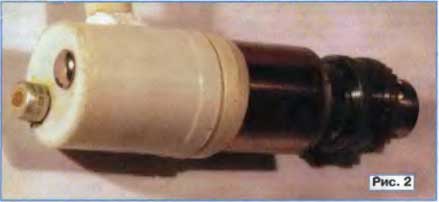
The appearance of the manufactured drill is shown in Fig. 2. It uses a collector DC motor DPR-62 with a rated supply voltage of 27 V. You can also use another DC motor that is suitable in terms of supply voltage, power and dimensions. When choosing it, you should pay attention to the maximum current consumption with a locked rotor. It should not exceed the collector current allowed for the KT829V transistor (8 A). For the DPR-62 engine, this current is about 2,5 A at a supply voltage of 20 V. The metal case of the tuning resistor R2 (SP5-16) installed outside the drill, connected through the resistor R1 to the plus of the power source, serves as the E1 sensor. Sensor E2 - rivet head.
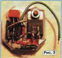
The control unit is mounted on a 4 mm thick aluminum plate as shown in fig. 3. First of all, transistors VT4 and VT5 are attached to the plate, the latter through an insulating gasket. The remaining elements are soldered to the terminals of these transistors. Transistors KT829V can be replaced by KT829 with other letter indexes. KT315G transistors should have as little reverse collector current as possible; KT315A or KT315V can be used instead. Diode - any of the series KD521, KD522. The assembled unit is glued to the end of the motor with double-sided adhesive tape, thus providing electrical insulation between the motor housing and the base of the unit. The drill should be powered from a constant voltage source that has good galvanic isolation from the 220 V network. When it is established, it is necessary to select the resistor R5 for the work performed to achieve optimal braking efficiency. If the run-out time of the rotor depends too much on the supply voltage of the drill, a stabilized source will have to be used. Author: A. Moskvin, Yekaterinburg; Publication: radioradar.net
Artificial leather for touch emulation
15.04.2024 Petgugu Global cat litter
15.04.2024 The attractiveness of caring men
14.04.2024
▪ Drawing of the Tower of Babel found ▪ A safe and inexpensive way to launch small satellites
▪ section of the site Encyclopedia of radio electronics and electrical engineering. Article selection ▪ article Apple trees will bloom on Mars. Popular expression ▪ article What are gases? Detailed answer ▪ article Work in wells, collectors, ventilation chambers. Standard instruction on labor protection ▪ article Frozen water. Focus Secret
Home page | Library | Articles | Website map | Site Reviews
www.diagram.com.ua |


 Leave your comment on this article: