|
|
ENCYCLOPEDIA OF RADIO ELECTRONICS AND ELECTRICAL ENGINEERING UA7TCW direct conversion transceiver for 3 MHz. Encyclopedia of radio electronics and electrical engineering
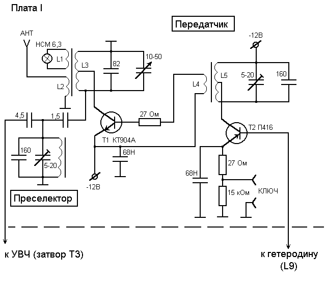
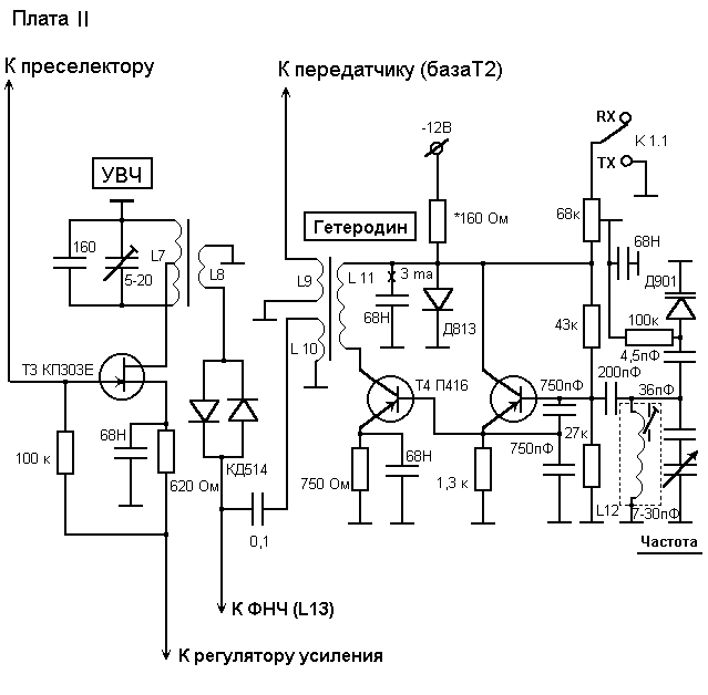
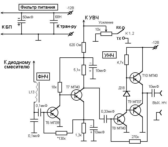
Encyclopedia of radio electronics and electrical engineering / Civil radio communications The transceiver is based on a direct conversion receiver. Transceiver parameters: P out .... 1 - 1,5 W Rx sensitivity .... better than 1 μV Frequency range .... 7,0 - 7,1 MHz Type of operation TX.... CW Type of operation RX.... SSB, CW U supply....12 - 13,8 V I consumption: TX....up to 250 mA RX....up to 20 mA (no signal received)The transceiver is powered in the field from 3 batteries of 4,5 V connected in series (KBS type). In stationary conditions - from a stabilized power supply with a load capacity of at least 300 mA. Receiver operation The signal from the antenna through the coils of the output circuit L2 and L3 and the preselector enters the UHF input (KP303). From the UHF output through L7 and L8 - to the mixer (KD514). The mixer receives a signal from the local oscillator through L11, L10 and C \u0,1d 3,5 μF. The frequency of the heterodyne signal = 3,55 - 1 MHz (2/XNUMX f of the working transceiver). From the mixer, all signals go to the low-pass filter through which only sound signals pass to the ULF and are amplified by it. Gain control is performed by a variable resistor "Gain" by changing the supply voltage of the UHF and the ULF voltage amplifier. In transmit mode, the TX / RX (transmit-receive) switch removes power from the UHF and ULF. Transmitter Operation The local oscillator continuously generates a signal 1/2 f working (3,5 - 3,55 MHz). Through coils L11 and L9, it enters the preliminary amplification stage of the transmitter (P416). When the key is released, due to the high resistance in the emitter circuit, RF currents sufficient to amplify the signal do not develop in it. When the key is pressed, the transistor switches to normal amplification mode and in the collector circuit, tuned to the second harmonic of the input signal, sufficient power is released to be transferred to the base circuit of the power amplifier (KT904A). From the power amplifier, the signal through the loop coils L3 and L2 enters the antenna. Coil L1 is used to power a light bulb - an indicator of the transmitter output settings. Since the transceiver in transmit mode does not emit a signal in the lower side band, but in the place of the suppressed carrier in the classic transceiver circuit, most stations giving a general call simply will not hear you (especially those operating in SSB). To do this, in the transmission mode, shift the local oscillator frequency "down" by 500 - 800 Hz. This function is performed in the local oscillator by a node consisting of a D901 varicap, a 68k tuning resistor, R = 100k, C = 4,5pF, and a K1 TX / RX switch (transmission-reception). Transceiver design The transceiver housing consists of a main chassis with front and rear walls screwed to it. The walls are attached to the chassis with the help of corners and screws. All three elements are made of duralumin 2mm thick. From above, the structure is closed with a U-shaped cover made of soft aluminum alloy. The bottom is screwed down - the lid. 3 rectangular windows 80x50mm are cut into the chassis for installation of three circuit boards above them. The boards are attached to the chassis with 4 screws each. The main installation of radio elements is made on three fiberglass boards using the printed wiring method. Mounting on a getinax or textolite basis is also possible. Board size 100x500mm. Board I - Preselector and transmitter. Board II - UHF and local oscillator. Board III - LLF and ULF. On the circuit diagram, they are designated as: I, II and III. Holes are drilled in the front panel for installing a switch (tumbler) PRD-PRM, a resistor "Gain" and the output of the KPI axes "Frequency" and "Tx setting", an indicator lamp is installed. Antenna terminals, grounding terminals, power connectors, key and headphones are attached to the back wall. Windows cut into the chassis allow soldering when setting up the transceiver without removing printed circuit boards (when performing printed wiring). Details All capacitors less than 1uF are ceramic or mica. All capacitors over 1 μF are electrolytic for a voltage of at least 15 V. All resistors are MLT-0,5 (possibly 0,125) and ratings + - 20%. Both KPIs are single-supported with an air dielectric and with elongated axes (in place). Inductors. L12 D = 8mm; wire d 0,35; 30 turns; core made of carbonyl iron or brass (with brass, the number of turns is 33). Enclosed in an aluminum screen 20x20mm. L13 Ferrite ring dia. 18mm HM 2000 D wire 0,23; 300 turns. All other coils are wound with PEL 0,35 wire on carbonyl iron rings made from central bushings of SB type cores. Ring coils L1, L2, L3 with a diameter of 10mm thickness 5mm. Carbonyl iron works very well, but care must be taken to avoid breaking the rings. Number of coil turns: L1 1 turn L2 a). High-impedance antenna 12 turns; b). Powered 75 Ohm 3 turns; V). With a power supply of 50 Ohm 2 turns. L3 20 turns, tap to KT904 from the 3rd turn, counting from the grounded end L4 3 turns L5 20 turns, tap from the fourth turn from the power L6 20 turns L7 20 turns, tap from the 6th turn from the grounded L8 6 turns L9 5 turns L10 3 turns L11 20 turns The final number of turns is selected when setting up the transceiver. Transceiver setup 1). ULF By selecting a resistor * 130k, the voltage on the collector of the MP40 transistor = 3-4 V. (The "Gain" resistor is in the right position according to the diagram, the signal is not applied to the ULF input). Selection by a resistor * 270k of the voltage at the ULF output equal to half the power supply (6 Volts). 2). Heterodyne. Setting the range 7,0 - 7,1 MHz with the L12 coil. Stretching the range by selecting the capacitance C \u36d * 2pF. Setting the frequency shift during transmission: a). TX/RX switch in RX position. With the control receiver, listen to the 7,0nd harmonic of the local oscillator (7,1 - 68 MHz) and tune in to zero beats. Without touching the control receiver, it will switch the transceiver to transmission (TX) and with a tuning resistor R = 500k, select the beat tone of 800-XNUMX Hz (by ear according to the desired sound). The control receiver must be in CW reception mode. 3). Mixer. By selecting the number of turns L10, adjust the maximum of the received signal and the minimum of noise. 4). UHF. Setting the contour for the maximum received signal at the middle frequency of the range. 5). Preselector. Setting the contour for the maximum received signal. 6). Transmitter. When the key is pressed and the equivalent of the antenna is connected (respectively equal to the resistance of the antenna-feeder system 50 Ohm, 75 Ohm or 1,5-2k) of the MLT-2 resistor, the indicator lamp "Setting before." setting the circuits of the PA and the pre-terminal stage of the transmitter, as well as the selection of the number of turns of the L4 coil. Then a real antenna is connected and the PA circuit is tuned again and possibly L4. The capacitance of the capacitor C \u82d * 10pF is selected in such a way that at the resonance of the output circuit, the rotor of the capacitor C \u50d XNUMX-XNUMXpF is approximately in the middle position. Recommendations 1). The old P416, MP39, MP40 transistors can be replaced with KT361 and the MP41 transistor with KT315. In this case, it is desirable to use transistors with the smallest possible h21 (less than 120) in the ULF, especially in the first stage of the ULF - in order to avoid self-excitation of the ULF. 2). The axes of closely spaced loop transformers on carbonyl iron rings should be located at 90` relative to each other to reduce mutual influence. Due to this, the transceiver does not need internal screens and partitions. 3). It is possible to improve the receiving part of the transceiver by increasing the number of low-pass filters to 2 or 3, to use a more highly efficient low-pass filter. four). In the case of strong local interference, one more circuit can be introduced into the circuit into the receiver preselector. 5). It is possible to increase the transmitter power by applying not 904V, but 12-24V to the KT26 emitter. But such an increase in output power up to 2-2,5 W can lead to undesirable processes: self-excitation of stages and frequency instability during transmission. In the event of an increase in power, it is necessary to turn on two diodes in parallel to the preselector circuit coil in anti-parallel to protect the UHF input from a powerful signal from its transmitter (KD503, 514) Antenna Tuning (High Impedance) LW An LW (half-wave beam) antenna with a high-impedance input is convenient for field work. An antenna 21 meters long is connected to the transceiver. The antenna should be suspended at a height of 7-8 meters. By selecting the length of the antenna and the number of turns L2, the radiated power is controlled by the field strength indicator at a distance of 20-30 meters from the antenna. For short-range "tourist" communications (up to 100 km), such an antenna works better with a suspension height of 2-2,5 meters. For more distant connections, it must be raised as high as possible. To match the output of the transmitter with other loads (50 or 75 ohms), you need to connect the appropriate dummy load through the SWR meter to the "Antenna" jack and by changing the number of turns L2 to get the SWR as close to 1,0 as possible. With the help of this transceiver, several thousand QSOs were made with all European territories of Russia, Ukraine, the Baltic states and several contacts with UA0A. An Inverted Vee, 50 Ohm antenna was used. Publication: N. Bolshakov, rf.atnn.ru
A New Way to Control and Manipulate Optical Signals
05.05.2024 Primium Seneca keyboard
05.05.2024 The world's tallest astronomical observatory opened
04.05.2024
▪ Synthesis of bones and enamel ▪ Looking at the sick makes us healthier ▪ Taiwan makes more and more motherboards ▪ The gadget is powered only by the heat of the human body
▪ section of the site Riddles for adults and children. Article selection ▪ article Deceived deceivers. Popular expression ▪ article Why do we hear echoes? Detailed answer ▪ article Machine-universal. home workshop ▪ article Automotive tachometer. Encyclopedia of radio electronics and electrical engineering ▪ article Coin through the sleeve. Focus secret
Comments on the article: a guest Good afternoon. Maybe I didn’t adjust the transceiver in the right way, but when the signal is amplified with a patensometer, the signal disappears, and in general it catches the signal. Now, if the adjustment was better described.
Home page | Library | Articles | Website map | Site Reviews www.diagram.com.ua |


 Arabic
 Bengali
 Chinese
 English
 French
 German
 Hebrew
 Hindi
Hindi Italian
 Japanese
 Korean
 Malay
Malay Polish
 Portuguese
 Spanish
 Turkish
 Ukrainian
 Vietnamese


 Leave your comment on this article: