|
|
ENCYCLOPEDIA OF RADIO ELECTRONICS AND ELECTRICAL ENGINEERING Thermal distortion in HiFi amplifiers. Part 2. Encyclopedia of radio electronics and electrical engineering
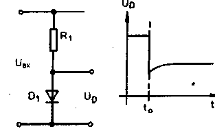
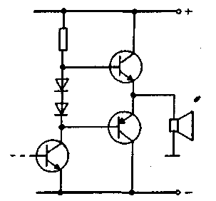
Encyclopedia of radio electronics and electrical engineering / Transistor power amplifiers Consider the simplest semiconductor circuit (Fig. 1), in which a semiconductor diode, together with a conventional resistor, form a series circuit. Such a circuit can be used in a HiFi amplifier (Fig. 2). If the circuit has been switched on for a long time, and some thermal equilibrium has been established, the output voltage Uout is constant. As the input signal increases, the current flowing through the circuit increases. Under its influence, the voltage drop across the diode slightly increases, and it begins to heat up more. Heating continues until a new thermal equilibrium is reached, and then everything stabilizes under the new conditions.
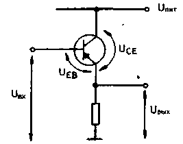
Most of the measurements are completed around this moment, content with registering a new thermal equilibrium. Everything would be fine if the resistance of the semiconductor diode did not change under the influence of heating, which, due to the negative temperature coefficient, leads to a decrease in the voltage drop across the diode. Therefore, there is both an increase and a decrease in the voltage drop, and all this occurs at different points in time. An increase in the voltage drop with an increase in current occurs almost instantly (with an "electronic" delay time of the order of pico- and nanoseconds), while its decrease is determined by the rate of heating of the diode together with the case (slowly, with a "thermal" rate). Heating is characterized by several time constants. The semiconductor junction itself, which has a small mass, heats up the fastest. The entire diode enclosed in the housing heats up much more slowly. Considering all these slowly decaying processes affecting the output voltage, it is easy to conclude that the diode’s response to a sudden change in current will first be a sudden change in voltage, the level of which will then gradually approach the initial value (moreover, the rate of approach will be determined by several time constants) . Thus, the transmission of regular current surges by the circuit is not ideal, "shoots" appear, the magnitude and decay time constant of which are not related to any electrical characteristics. The resulting distortions are purely thermal in origin. It is obvious that in this case it makes no difference whether we are talking about discrete diodes and transistors, or about integrated circuits. Since there are both massive and miniature diodes, the spread of time constants can be very wide. Let us subject the simplest emitter follower to the same unusual analysis, the scheme of which is shown in Fig. 3. Let's ask ourselves a question, does such a circuit have a low-frequency time constant (lower limiting frequency) and the frequency-dependent transients caused by it? Based on textbooks, specialists and non-specialists answer in unison - NO! We, taught by previous experience, take a closer look at it.
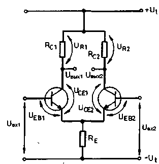
Let us assume that the circuit has been switched on for quite a long time, the transistor and its environment have already reached some thermal equilibrium, at which power P1 is dissipated on the transistor, maintaining the temperature of the transistor constant. Uce1*Ic1=P1 Let's change the operating point of the transistor by significantly changing the input voltage. As soon as the collector current of the transistor changes (although here it would be possible to take into account the time constant), the emitter-collector voltage will also change. The transistor will now dissipate power P2 Uce2*Ic2=P2, which is different from the above, and this will lead to a change in the established temperature of the transistor. To illustrate the distortions that arise in this case, from the set of parameters to be controlled, we will choose one of the most easily measured - the voltage Ueb In the steady state, at the output of the emitter follower there is Uout1=Uin1-Ueb1. which can be easily measured with a multimeter. The change in the input voltage at the first moment almost completely falls on the output. However, now the transistor has a different operating point, corresponding to the power dissipation P2. This affects the voltage Ueb (-2 mV/°C) and causes an offset (drift) in the output voltage (because the transistor is now either a little colder or warmer compared to the previous state). The voltage change must be added (with the correct polarity) to the output voltage, and the thermal time constant determined on a case-by-case basis. Here are the key questions: - what is the value of the thermal time constant; How a transistor heats up or cools down at a new operating point depends on its state at the previous operating point. If the transistor worked in the power matching state (Uce=0,5Upit), then it responds to any change in the operating point by cooling down. Therefore, in this case, on the influence of some small constant control voltage, the transistor always produces a noise signal of the same type, which is added to the output signal. If the operating point of the transistor differs from the agreed upon, at the new operating point the transistor can both cool down and heat up. In this case, the polarity of the interference signal appearing at the output will depend on the polarity of the control signal. Depending on the control signal, the thermal noise signal can now be added to or subtracted from the output signal. Consider a differential amplifier circuit (Fig. 4), which is also of interest from a historical point of view - several decades ago, the thermal distortions generated by this circuit constituted the main part of all thermal distortions.
Two situations are possible. In the first case, when the differential amplifier is matched in power, the action of the control signal leads to cooling of both transistors (having almost the same dimensions). Then, in the amplified signal available on the transistor collectors, a new, in-phase component appears (under the influence of cooling, Ueb increases, the collector current increases and, as a result, the collector voltage decreases). In unfavorable cases, this component can spread further in the amplifier and, for example, "knock" the setting of the operating point of a push-pull output stage, or cause unpleasant shifts in the operating points of other stages. It is usually said that there is no significant interference in the output differential signal. The magnitude of the resulting common-mode signal is proportional to the input control voltage and the common-mode voltage gain, which is, to a good approximation, determined by the ratio of the collector and emitter resistances. Since these values are usually quite close for audio frequency amplifiers, we can assume that the common-mode signal is amplified several times (for example, 1 ... 10). Therefore, if there is already a sufficiently high level differential signal in the stage, the common-mode voltage value can be quite large. This signal (common mode) is not audible by itself, but it can disturb the operating points of subsequent stages. By the way, a change in ambient temperature, which leads to a change in the temperature of semiconductor devices, has exactly the same effect (for example, when using an amplifier on a hot sunny day or in frosty weather). Both considered effects are summed up. Thus, when designing HiFi amplifiers, it is no longer enough to take care of static thermal coupling. It is also necessary to take into account the above-mentioned dynamic common-mode effects. In the second case, when the differential amplifier operates with a power mismatch, under the influence of the control signal, transients occur at the output, which have a thermal time constant. In magnitude and frequency, they are in this case comparable to the control signal, they can be detected as distortions of the useful differential output signal, measured or heard in an appropriate way. Since one of the transistors will heat up and the other will cool down, an anti-phase noise signal arises, which is practically indistinguishable from the useful signal. A tricky question is the value of the thermal time constant. There is no data on this in any catalogs, and one can rely here only on some experimental facts. Some of these experimental data are published in highly specialized short-circulation publications of a number of interested companies (for example, Tektronix, Philips, Ates, etc.). For them, these data were not too unexpected. Transistor semiconductor pn junctions of a "decent" size, such as for example 2N3055 (we are not talking about the semiconductor device itself in the package yet, the dimensions of which may also depend on the series and manufacturer) can thermally track (i.e. heat up / cool down) frequencies up to the upper limit - about 1 kHz. Devices with a smaller p-n junction, such as BC107, or even less, track frequencies up to a frequency of 90 kHz (!). For surface mount elements (SM - Surface Montage) and integrated circuits, the cutoff frequency is even higher. Naturally, there is a good thermal contact between the semiconductor chip and the package, and the large thermal constant of the package tends, in accordance with the amount of heat transfer from the contact, to dampen temperature fluctuations. I think that it is now clear that a DC amplifier (for example, the emitter follower shown in Fig. 3, which is also a kind of UPT) has the same lower (!) Cutoff frequency as, for example, a 200 MHz emitter follower. These audio frequency distortions cannot be measured by traditional methods. The principle often used in measurements, "wait until the circuit warms up," precisely circumvents the problems considered here. But how can you detect this effect when listening to a piece of music through a HiFi amplifier? Of course, we are most interested in the magnitude of the effect. From the measurements carried out, it turned out that the secondary signal arising in this way in the amplifier (which can be perceived as distortion) can easily reach 5 ... 20% of the amplitude of the useful signal. It is quite possible that many readers have plastic-cased HiFi amplifiers resting on bookshelves, which are all right with the "entourage", and meanwhile, they have very strong thermal distortion. They do not necessarily distort everything and always, but only certain melodies and in certain sound combinations (after a blow, etc.). And with traditional methods of measuring distortion, the amplifier looks very good. Author: S.GYULA; Publication: N. Bolshakov, rf.atnn.ru
The world's tallest astronomical observatory opened
04.05.2024 Controlling objects using air currents
04.05.2024 Purebred dogs get sick no more often than purebred dogs
03.05.2024
▪ Graphene's success is hindered by silicon particles ▪ 56Gbps In-System Interface Receiver ▪ Red light can improve vision
▪ section of the site Signal limiters, compressors. Article selection ▪ article If the enemy does not surrender, he is destroyed. Popular expression ▪ article How long ago did they start to parody the classics? Detailed answer ▪ article Functional composition of Signum TVs. Directory
Home page | Library | Articles | Website map | Site Reviews www.diagram.com.ua |


 Arabic
 Bengali
 Chinese
 English
 French
 German
 Hebrew
 Hindi
Hindi Italian
 Japanese
 Korean
 Malay
Malay Polish
 Portuguese
 Spanish
 Turkish
 Ukrainian
 Vietnamese


 Leave your comment on this article: