
|
|
ENCYCLOPEDIA OF RADIO ELECTRONICS AND ELECTRICAL ENGINEERING Radio pulse frequency multiplication. Encyclopedia of radio electronics and electrical engineering
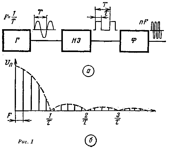
Encyclopedia of radio electronics and electrical engineering / Note to the student When designing short-wave amateur radio stations and measuring instruments that meet modern requirements for stability, calibration accuracy and frequency reading on a scale, significant difficulties are encountered. The main one is obtaining highly stable, accurately calibrated reference frequencies. The easiest way to obtain fixed frequencies is to use a crystal oscillator with resonators for the appropriate frequencies. However, it is not always possible to select quartz resonators for the required frequencies, and in addition, the resonators have a frequency spread that cannot always be compensated by tuning elements. Other common ways to obtain fixed frequencies are direct low frequency oscillator frequency multiplication and heterodyning. The method of direct frequency multiplication lies in the fact that harmonic oscillations from the generator G are fed to the input of the nonlinear element of the NE (Fig. 1, a), which are converted into a sequence of rectangular, cosine or other video pulses with a period T and a pulse duration t.
The spectrum of video pulses (Fig. 1b) consists of harmonics that are multiples of the fundamental frequency, the amplitude of which decreases with increasing harmonic number. Therefore, the use of harmonics with large numbers is impractical because of their low level and the difficulty of filtering the desired harmonic (using the F filter). The energy output spectrum of the multiplier characterizes the conversion efficiency
where Рс is the power of the useful harmonic; Рtot - the power of all components. The "purity" of the signal at the NE output is characterized by the side harmonic coefficient
where Up is the amplitude of the useful harmonic, Ub is the amplitude of the neighboring harmonic. It can be seen from the table that with an increase in the number of the used harmonic, the efficiency conversion decreases very quickly. Therefore, the use of a video pulse multiplier is advisable when the multiplication factor is not more than a few units (usually 3-5). To obtain large multiplication factors, it is necessary to turn on several multiplication and amplification stages in series with selection elements at the output.
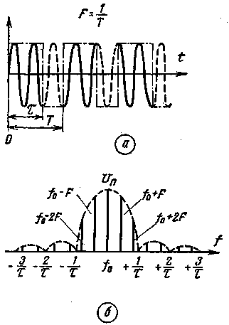
The spectrum of short rectangular video pulses is richer in harmonics: the table shows that n decreases more slowly with increasing harmonic number than in the case of cosine pulses, but is still a small value. The coefficient of side harmonics is large, and complex selective devices are required to attenuate the harmful components of the spectrum. If the frequency grid is formed by the heterodyning method, then there are problems with the selection of quartz resonators, fitting or adjusting their frequency. Radio pulse frequency multipliers The method of radio pulse frequency multiplication, which allows the use of harmonics up to 1000, was first proposed in our country by V. I. Grigulevich in 1952. A remarkable property of this method is also the possibility of obtaining an almost ideal spectrum. This is achieved by the fact that the converted signal is given the form of a sequence of pulses with high-frequency filling (radio pulses) that satisfies certain conditions. For radio pulses, as well as for video pulses (see Fig. 1, b), the shape, width, and distance between harmonics of the spectrum are determined by the shape, duration, and repetition rate of the pulses. In addition, the pulse filling frequency determines the position of the maximum of the spectrum envelope on the frequency axis. The position of the harmonics on the frequency axis depends on the law of change in the initial phase of oscillations from pulse to pulse. If the initial phases of the high-frequency filling of individual pulses change according to a random law, then the position of the harmonics on the frequency axis also takes on random values. The spectrum of such a radio pulse sequence will be continuous (noise) within the envelope. If the initial phases of the radio pulses are coherent, that is, the radio pulses are, as it were, “cut out” from one continuous sinusoidal oscillation (Fig. 2, a), then the maximum of the spectrum envelope (Fig. 2, b) coincides with the filling frequency (fo) and the position of the harmonics on the frequency axis is determined by the filling frequency, which is a disadvantage of this case. Such oscillations can be considered as continuous, modulated by rectangular pulses.
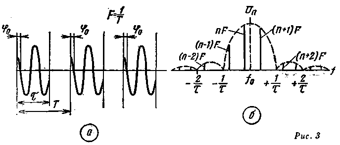
If the initial phases P3 of the radio pulses are the same and constant (there is a constant phase shift between the high-frequency filling of adjacent pulses), then the sequence of pulses becomes purely periodic (Fig. 3a). The spectrum of such a sequence (Fig. XNUMXb) consists of harmonics that are multiples of the repetition frequency and does not depend on the filling frequency.
Therefore, in this case, the effect of multiplying the repetition frequency takes place. The frequency of the harmonic with maximum amplitude is near the duty cycle. The attenuation of spurious harmonics, in particular two adjacent ones, can be obtained significant, as a result of which the requirements for the filter at the output of the multiplier can be significantly reduced. The rate of decrease in the amplitudes of adjacent harmonics depends on the pulse duration. The larger m, the closer to fo and more often the zeros of the envelope are located, the faster the harmonics decay. This means that in order to increase the efficiency and reduce the coefficient of side harmonics, it is necessary to increase the ratio m/T. Practically achievable maximum values of m/T lie in the range of 0,9-0,95. In this case, the coefficient n reaches the value of 0,9, and y=0,1. But even with the ratio m/T=0,5, radio pulse multiplication has a significant advantage over video pulse multiplication, providing the values n=0,5 and y=0,6. Methods for constructing radio pulse frequency multipliers. On fig. 4 shows a block diagram of a local oscillator built on the principle of radio pulse frequency multiplication.
Oscillations from the KG quartz oscillator are fed to the non-linear element of the NO. The video pulses formed after the nonlinear element are fed to the control element of the RE, which creates the conditions for the occurrence or breakdown of oscillations of the self-oscillator G. The stability of its frequency is not essential, since only the change in the amplitude of the working harmonic depends on it, while the stability of the harmonic frequency is determined by the stability of the quartz generator. It is necessary that the process of the occurrence of high-frequency filling oscillations occurs in the same way for each pulse (Fig. 3a). A similar process can only be carried out in self-oscillators. Practical circuits can be constructed in different ways, depending on which of the parameters is used to disrupt self-oscillations. In low-power generators of the short-wave range, it is advisable to use a circuit with a change in the equivalent resistance of the circuit. The principle of operation of such a circuit can be explained with the help of Fig. 5.
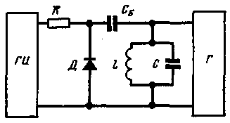
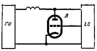
The LC circuit is an oscillatory system of the self-oscillator G. Parallel to the oscillatory circuit, a diode D is connected through the separating capacitor SB. Bipolar video pulses from the GI generator are fed to the diode through the resistor R. At the moments of time when positive pulses arrive at the diode, the diode is locked and self-oscillations begin to occur in the generator. During negative pulses, the diode opens and shunts the circuit. Oscillations of the generator break down. Resistor R must be chosen so that when the diode is locked, it does not shunt the circuit much. Instead of a diode, you can use a transistor or a lamp. On fig. 6 shows a circuit in which the slope of the lamp characteristic is used as the driving parameter.
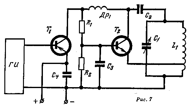
When pulses are received, the anode voltage of the lamp rises, the anode current increases, and high-frequency oscillations occur. In the absence of a pulse, the voltage at the anode drops and the oscillations break down. A similar slope control can be implemented in the grid circuit of the lamp. On fig. 7 shows a variant of the circuit using transistors.
There are circuits in which the feedback coefficient serves as the excitation parameter. Pulse shaping devices must be well shielded to prevent harmonic leakage. Good filtering of power circuits, compliance with general installation rules and the use of decoupling are required. One of the radical methods of combating spurious interference and radiation is the formation of signals at low levels. Therefore, the use of transistor circuits is especially advisable. At the same time, the dimensions of the equipment, weight, and energy consumption are also reduced. It is possible that for designers of amateur shortwave and measuring equipment the method described above for obtaining fixed frequencies will be tempting. Then, using the above principles for constructing circuits, introducing elements of creativity into them, designers will be able to find their place for this method among other technical solutions. Literature: 1. V. I. Grigulevich. A new way to multiply frequency. "Elektrosvyaz", 1956, No. 6.
Author: T. Labutin (UA3CR); Publication: N. Bolshakov, rf.atnn.ru
A New Way to Control and Manipulate Optical Signals
05.05.2024 Primium Seneca keyboard
05.05.2024 The world's tallest astronomical observatory opened
04.05.2024
▪ Battery absorbing carbon dioxide ▪ Commercial graphene super battery ▪ Economy hatchback Peugeot 208
▪ section of the Electrician website. PUE. Article selection ▪ article Endless dead end. Popular expression ▪ article What is the name of the masts of a sailing ship? Detailed answer ▪ article Work on grinding and grinding machines. Standard instruction on labor protection ▪ article The first electric battery. physical experiment
Comments on the article: Alexey The original article by Labutin was published in Radio magazine #12/1969
Home page | Library | Articles | Website map | Site Reviews www.diagram.com.ua | ||||||||||||||||||||||||||||||||||||||||||||||||||


 Arabic
 Bengali
 Chinese
 English
 French
 German
 Hebrew
 Hindi
Hindi Italian
 Japanese
 Korean
 Malay
Malay Polish
 Portuguese
 Spanish
 Turkish
 Ukrainian
 Vietnamese



 Leave your comment on this article: